Download
1 / 28
280 likes | 382 Vues
ASEE Annual Conference The Division for Experimentation and Laboratory-Oriented Studies, Session 1526 Saint Louis, Missouri June 19, 2000.

E N D
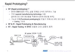
ASEE Annual Conference The Division for Experimentation and Laboratory-Oriented Studies, Session 1526 Saint Louis, Missouri June 19, 2000 An Integrated Facility for Rapid Prototyping Rhonda Kay Gaede, B. Earl Wells The University of Alabama in Huntsville Department of Electrical and Computer Engineering Huntsville, AL 35899 UAH
Disclaimer • This material is based upon work supported by the National Science Foundation under Grant No. 9751482. Any opinions, findings, and conclusions or recommendations expressed in this material are those of the authors and do not necessarily reflect the views of the National Science Foundation.
Abstract • In 1997 the Electrical and Computer Engineering (ECE) Department at the University of Alabama in Huntsville (UAH) received a grant from the National Science Foundation to develop a laboratory for the rapid prototyping of digital circuits. This multipurpose laboratory was designed to allow interactive instruction to minimize the learning curve associated with modern electrical design automation tools. The laboratory fully supports hands-on, non-trivial student design experiences. It is comprised of a set of networked PCs that host a wide range of CAD tools including design capture (schematic capture and hardware description language based), simulation, and rapid prototyping facilities that utilize reprogramable FPGAs and CPLDs. The creation of this laboratory has had a direct effect on a number of courses that span a large portion of the ECE undergraduate design curriculum at UAH. • In these classes, students have expressed a renewed interested in the design process and have been able to interactively experiment in a meaning manner with alternative design methods. The facility has been used to create and prototype a broad spectrum of designs which were part of both introductory and advanced courses. Projects have ranged from application-specific medium scale logic circuit design to the design and rapid prototyping of complete microprocessors. A key innovation brought about by this facility and the associated curriculum changes is that students now are introduced to rapid protyping of basic designs using behavioral tools (VHDL) and structural tools (schematic capture) very early in their undergraduate career. This early exposure is constantly re-enforced as students progress throughout their course work. This presentation provide an overview of the designs and curriculum innovations that have been made possible under the auspices of this grant.
Laboratory Equipment • 12 networked PCs (Dual boot running Windows NT 4.0/Linux ). • 2 PC based Logic Analyzers with additional low end PC's to act as hosts • 6 20MHZ oscilloscopes • Networkable HP Laser Printers • 12 Altera UP-1 Rapid Prototyping Boards (total of 24 used thus far in project,10 donated 14 purchased). • Altera Max+Plus II Edition Software (for PCs and Suns) • 4 Xilinx FPGA Demoboards -- with 3000 and 4000 series Xilinx chips – equivalent to Altera UP-1 • 10 Xilinx XS40 Demo boards (8031 up with RAM and 4000 series Xilinx parts) • Xilinx Foundation V2.1 Software • Projection System with lowend PC • IKOS large reconfigurable logic accelerator. • 2 Modular Circuit Technology -- MOD EMUP-A Universal Programmer and Testers
Implemented Course Changes • CPE/EE 422/502 - Advanced Logic Design • EE 201 - Digital Logic Design Lab • CPE 427/437- Computer Engineering Design I & II • CPE 582 - VLSI Design Using Synthesis and Hardware Description Languages • CPE 493 - VLSI Design II • CPE 197 - Engineering Methods Using C
Planned Course Changes • CPE/EE 302 Design of Digital Computer • Simulate VHDL Models of modules of computer design such as aritmetic logic unit (ALU) and datapath • CPE 433 Advanced Techniques in Computer Design • Simulate models of a RISC processor • Replace modules of the processor with student written models to explore the design space
CPE 197 – Computer Methods in Engineering • Solution of engineering problems using a digital computer. Hardware structure of the stored-program computer; machine language programming, engineering approximation of dynamic systems; flowcharting and algorithms. Practice in solving engineering problems on the university computers using “C”.
CPE 197 The projection system in the Rapid Prototyping Laboratory has been incorporated on a movable cart with a PC. Instructors in CPE 197 can use the projection system to work examples in class as an alternative to having a lab large enough for each student to have a PC.
EE 201 - Digital Logic Design Lab • Experiments on logic gates, combinational logic circuit design, flip-flops, sequential circuit design, counter registers, and shift registers. • Students use the same Altera software used in the Rapid Prototyping Laboratory to simulate their designs. They design their circuits, simulate them using the Altera software, and then build them and observe the results using oscilloscopes and other test equipment.
EE 201 Students normally work individually to build their circuits using the prototype boards available for their use.
EE 201 By learning to use the Altera tools in this early class, students are ready to focus on concepts rather than tools in the advanced logic class.
EE 201 In two of the later labs, students use programmable logic to implement one of their designs. They describe this design using very basic VHDL.
CPE/EE 422/502 Advanced Logic Design • Advanced concepts in Boolean algebra, use of hardware description languages as a practical means to implement hybrid sequential and combinational designs, digital logic simulation, rapid prototyping techniques, and design for testability concepts. Focuses on the actual design and implementation of sizable digital design problems using representative Computer Aided Design (CAD) tools.
CPE/EE 422/502 Students enter their designs using either schematic capture or VHDL, simulate them, and download them to the Altera University boards.
CPE/EE 422/502 The two programmable Altera devices included on the university development board allow significant projects to be implemented.
CPE 427/437 Computer Engineering Design I & II • Senior design project course involving microcomputer based systems. First design course on digital system design. Case studies of legal, economic, and ethical design issues. • Senior design project course involving microcomputer based systems. Second design course on digital system design. Oral presentations and written reports are required.
CPE 427/437 Students in the computer engineering design sequence take a system design from concept to implementation. They work in teams to implement both hardware and software components of their system.
CPE 427/437 Some of the projects involve the use of programmable logic devices. Additionally, the students use the projection system in the RPL for critical and final design review presentations. Students in the course are required to document their designs on a web page.
CPE/EE 493 - VLSI Design II • Advanced experience with CAD tools for VLSI design, IC testing. Design Project from CPE/EE 492 to be fabricated and tested. Implementation and verification of test programs, IC testing and trouble shooting, legal , economic, and ethical design issues. Oral presentations and written reports are required. • Students reimplement the designs they completed in the first semester and sent off to MOSIS for fabrication using VHDL. They then simulate the design, download it to an Altera chip and test it. When the MOSIS chips come in, the board used with the Altera chip can be used to test the MOSIS chip.
CPE/EE 493 An instructor-designed and built board is customized and used to test the chips designed using full custom standard cell techniques during the first semester of the course.
CPE/EE 493 The boards have three donated Altera chips on each of them. The board is initially wired for a simple circuit for which a test program is provided.
CPE/EE 493 Students wire wrap their boards to customize them for their particular design, whether implemented in programmable logic or fabricated by MOSIS.
CPE 582 - VLSI Design Using Synthesis and HDLs • Modern VLSI design techniques and tools, such as silicon compilers and (V)HDL modeling languages. Students are expected to design and simulate a VLSI chip.
CPE 582 Students in this course use the Altera software available in the RPL and on the SUN machines pictured here for layout of their synthesized designs. The PCs in the lab can be used in their Linux mode to access the other software used in this course.
CPE 595 – MicrocomputerDevelopment Systems • Development of general purpose stand-alone microprocessor systems using a microprocessor development systems. • Project: The Reconfigurable Glue Logic Microprocessor Interfacing Trainer (RLT): the Reconfigurable glue Logic microprocessor interfacing Trainer, RLT, is a device that is to be designed to give future computer and electrical engineering students at UAH a platform through which they can easily prototype bus-level microprocessor interfacing designs in a classroom setting without the need of applying expensive and time consuming prototyping techniques. The trainer will use a medium size reconfigurable logic device which the students will configure using standard CAD software thereby enabling a number of bus-level interfacing experiments to be performed between the microprocessor and nonvolatile memory (FLASH or EPROM), SRAM, and DRAM memory. The RTL is to be designed so that it can be interfaced to any computer that has a standard RS232 serial interface and a basic terminal program.
CPE 427/437 One student project using the Altera parts was the Enunciator, which is very similar to a scrolling marquee. It will display a message on an 8x64 LED matrix. The Enunciator is menu driven from a HyperTerminal session that is connected to the proto-board via a serial connection. It has the capability to display all printable characters, display very simple graphics, and several different erase methods. Each message is user defined and can be up to 8 characters long and can be scripted to print up to 10 messages. If the message series option is chosen, a different erase method may be used after each message is displayed.
CPE/EE 422/502 Students in the Rapid Prototyping Laboratory work with the instructor on their design projects.