Download
1 / 14
140 likes | 256 Vues
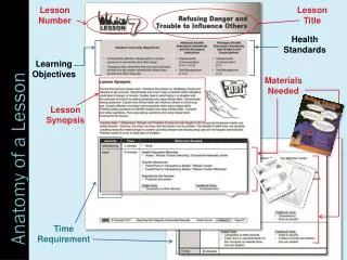
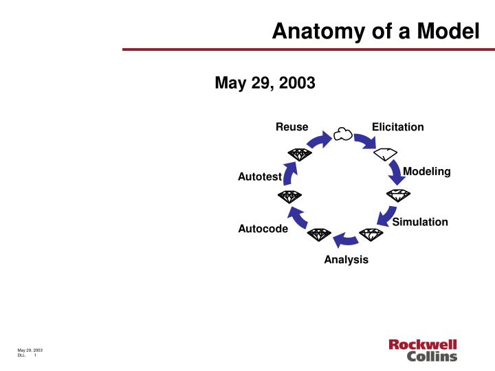
Reuse. Elicitation. Modeling. Autotest. Simulation. Autocode. Analysis. Anatomy of a Model. May 29, 2003. MBD project purpose Build a MBD framework and document design process Collect metrics for bid and proposal. MBD project details Schedule is 1 year from start to finish.

E N D
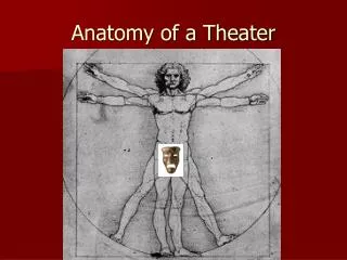
Reuse Elicitation Modeling Autotest Simulation Autocode Analysis Anatomy of a Model May 29, 2003
MBD project purpose Build a MBD framework and document design process Collect metrics for bid and proposal MBD project details Schedule is 1 year from start to finish Model Based Development work at Rockwell Collins
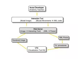
The anatomy of a model • The Anatomy of a Model is a white paper written for the MBD project • Purpose of paper is to • Define the major parts of a model • Identify areas for future research • Why write this paper? • Improve team discussions by providing a common understanding of what a model is. • Focus of the paper • The application layer of software
Levels of a model • A model is a preliminary representation, serving as the plan from which the final object is to be constructed. • Requirements view is • Requirements collection • Requirements mapping to the model • Logical view is • Requirements implemented with logical connections • Physical view is • Mapping of logical levels to physical hardware
Model concepts • The value of a model increases with increased model fidelity • Engineers trust the model • The final system understanding increases with models that mimic the way people think about problems • Engineers understand the model • Relationship • Direct • Code Generation • Doc Generation • Test Vector Generation • Indirect • Requirements Validation • Algorithm Design • Prototyping
Model primitive • Primitives are the building blocks of the model • Primitives may be • Textual • Graphical • Key primitive concepts • Primitives are reused and common across the corporate enterprise • The set of primitives is often a subset of all of the primitives available in a syntax • Safety reasons • Simplification for the user • Customization for a specific need
Requirements level 6 – requirements view • Requirements are everything you need to know to build the correct system and nothing more – David Parnas • Requirements are • Textual (… shall ) • Properties (… mathematical shall) • Graphical (SCADE) • Inter level communication • Link meta data • Formal proof • Information is used to • Design and build the system • Assess change impact • Communicate with customers
Component level 1 – logical view • Components are • The primary specification mechanism • A single syntax or a mix of syntaxes (tool dependant) • Examples include • Data flow tool (SCADE) • State chart tool (SAFE STATE, Machines (SSM) SCADE and Esterel Studio) • Graphical editor tool (VAPS, DWB) • C++ or ADA 95 • Information is used to • Generate software and documentation • Generate test vectors for MCDC • Model check requirements properties • Simulate and test requirements behaviors
Partition level 2 – logical view • Partitions are • Component binders (architecture) • Isolation barriers (functionality of a partition isolated from all other partitions except through interface) • Task managers • Bound to one and only one processor • Information is used to • Generate software and documentation • Simulate and test individual requirements behaviors • Make software architecture decisions
Systems logical level 3 – logical view • Systems logical level is • Implementation of all functional requirements • Implementation of all logical data flow connections • Information is used to • Simulate and test the behavior of the system • Check for interface • Constancy • Completeness • Check for requirements coverage • Make system architecture decisions
Software architecture level 4 – physical view • Software architecture is • Mapping of partitions into the hardware • Sizing of partition resource needs to the hardware resources available • Information is used to • Build and integrate software on the target hardware • Generate design documentation on the HW and SW integration
System architecture level 5 – physical view • System architecture is • Mapping and sizing of each system logical block into a hardware resource • Implementation of performance requirements • Information is used to • Configure hardware resources (network busses) • Analyze the system • Safety • Realizability (will it fit) • Reliability (will it work tomorrow) • Performance
Design tools specific map into models • Prototype developer • Prototyper developer build VAPS NG/Simulink/Scade models in their prototype of the design • Prototype models become requirements • System architect • Write shallow requirements – supplement with models (psudu code -> model) • Allocate requirements to partitions • Map partitions to HW • Software architect • Allocate requirements to components • Bind components to partitions • Validator • Test functional requirements in level 2,3 (simulator & model checkers) • Test performance requirements in level 5 • Test HW/SW integration in level 4 • Verifier • Verifiers use qualified code generator and qualified test vector generators for SW design requirements and MCDC * From Prover Technologies
Conclusion • Introduce the MBD project • Present “The Anatomy of a Model” • Discuss the map of tools into the model