Download
1 / 50
510 likes | 649 Vues
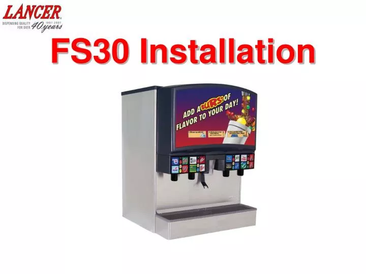
FS30 Installation. INSTALLATION OVERVIEW. Injected Flavor BIB Pumps. Syrup BIB Pumps. CO2. CO2. Front Syrup, Water & CO2 Connections. Water. Water. Syrup BIB. Injected Flavor BIB. Brand Syrups (5 to 1 ratio) Injected Syrup Flavors (20 to 1 ratio). INSTALLATION OVERVIEW. 3/8” line.

E N D
INSTALLATION OVERVIEW InjectedFlavor BIB Pumps Syrup BIB Pumps CO2 CO2 Front Syrup, Water & CO2 Connections Water Water Syrup BIB Injected Flavor BIB • Brand Syrups (5 to 1 ratio) • Injected Syrup Flavors (20 to 1 ratio)
INSTALLATION OVERVIEW 3/8” line 1/4” line 75 psi CO2 Source Water Source INSTALLATION OVERVIEW Barb unions and reducers connect lines to Bundle tubing Water Regulator BIB BIB Water Booster BIB BIB BIB BIB BIB BIB BIB BIB BIB BIB BIB BIB BIB BIB BIB BIB BIB 11
DRINK OPTIONS 4 3 1 2 FS - 14 shown above 16 Possible Brand Syrup flavors from 4 nozzles • 4 brand valves , 3 brand valves , or 2 brand valves 12 Possible Injected Syrup flavors or waters • 3 Injected Flavors for each nozzle • Buttons programmable to activate water or soda dispense. 16 Possible Soda drinks 8 Possible Plain Water drinks (with programming). • Plain water programmable on nozzles #2 and #3 only
CONFIGURATION OPTIONS ICE FS30-16 = 4 Push Lever PUSH ICE FS30-15 = 3 + 1 Push Lever PUSH ICE FS30-14 = 2 + 1 + 1 Push Lever PUSH FS30-13= 2 + 1 + 1 ICE Push Lever PUSH ICE ICE ICE ICE ICE PUSH\ PUSH\ PUSH\ PUSH\ PUSH\ FS30-10 FS30-11 FS30-12 FS30-8 FS30-9
VALVE PANEL LAYOUT 4 3 2 1 Note: Brands covering 2 positions take top designator ICE S4-3 S3-1 S3-3 S2-1 S4-1 S1-3 S2-3 S1-1 IS3-1 IS4-1 IS2-1 IS1-1` Push Lever IS3-2 IS2-2 IS1-2 IS4-2 S1-4 S4-4 S3-2 S2-2 S2-4 S1-2 S3-4 S4-2 IS3-3 IS4-3 IS2-3 IS1-3 PUSH 4 2 1 3 S=Brand Syrups IS= Injected Flavors Nozzle Number - Button Position
PANEL LAYOUTALIGNMENT RECOMMENDATIONS Ring 3 Ring 1 Ring 1 (Inner most) Ring 2 Ring 4 Ring 2 Ring 3 Ring 4 (Outer most) Drink Categories #1 Bright Colors (Red Flash, Big Red, Orange, Fruit Punch) #2 Thin Dark Colors (Diet Cola, Diet Dr. Pepper, Teas) #3 Light Colors (Lemonade, Lemon Lime, Sprite, 7-Up) #4 Dark Colors (Cola, Root Beer, Dr. Pepper) Ring 1 - Category 2 & 3 drinks Ring 2 - All category drinks Ring 3 – Category 1, 2 & 4 drinks Ring 4 - Category 1, 2 & 4 drinks
BRAND LEGEND ICE Push Lever 4 3 2 1 PUSH S2- 2 S1 - 1 S3 - 3 S1 - 1 Equals Syrup to Nozzle 1, Position 1 S2 - 2 Equals Syrup to Nozzle 2, Position 2 S3 - 3 Equals Syrup to Nozzle 3, Position 3
INJECTED FLAVOR LEGEND ICE Push Lever 4 3 2 1 PUSH IS2 - 1 IS3 - 2 IS4 - 3 IS2-1 Equals Injected Syrup, Nozzle 2, Position 1 IS3-2 Equals Injected Syrup, Nozzle 3, Position 2 IS4-3 Equals Injected Syrup, Nozzle 4, Position 3
SODA AND WATER LEGEND 4 3 2 1 Soda Soda Soda Soda or Water or Water SODA Inbound Water to carbonator for soda WATER Inbound Waterfor non-carbonated drinks
INLET CONNECTIONS Injected Flavors Inlet Connections Brand Syrup and CO2 Water Inlets
SYRUP/WATER/CO2 INLET DIAGRAM Injected Syrup Flavor Inlets ICE S4-1 S2-3 S4-3 S2-1 S1-1 S1-3 S3-3 S3-1 IS3-1 IS2-1 IS4-1 IS1-1 Push Lever IS1-2 IS3-2 IS4-2 IS2-2 S3-4 S3-2 S2-2 S2-4 S4-2 S1-4 S4-4 S1-2 IS1-3 IS3-3 IS2-3 IS4-3 4 2 3 1 PUSH Brand Syrup Inlets CO2 Inlet IS4-1 IS2-1 IS1-1 IS2-2 IS3-1 IS1-2 IS2-3 IS1-3 IS4-2 IS3-2 IS4-3 IS3-3 Water Inlets S 1-2 S 2-4 S 2-1 S 2-2 S 1-4 S 3-2 S 2-3 S 4-4 S 4-1 S 3-3 S 3-1 S 1-3 S 4-2 S 3-4 S 1-1 S 4-3 WATER FOR SODA WATER
BRAND INLET CONNECTIONS Brand Syrup Inlet Connections • 16 Brand Syrup Inlets • 3/8” hose Inlet Fittings
BRAND SYRUP INLETS \ IS4-1 IS2-1 IS3-1 IS1-1 IS4-2 IS2-2 IS3-2 IS4-3 IS2-3 IS1-2 IS3-3 IS1-3 Injected Flavor Inlets S 4-3 S 1-2 S 4-4 S 3-4 S 3-2 S 1-1 S 2-3 S 3-3 S 2-1 S 1-3 S 4-2 S 4-1 S 2-4 S 2-2 S 1-4 S 3-1 PLAIN WATER WATER FOR SODA Brand Syrup Inlets Water Inlets CO2 Inlet
INLET CONNECTIONS (BRANDS) 3/8” line Hook-up Fittings 16- 3/8 barb unions Connect to Bundle Tubing
INJECTED SYRUP FLAVOR CONNECTIONS 1/4” hose connections To assure splash plate will latch, turn clamps to side after crimping • 12 Inlet connections for Injected Flavors • 1/4” hose connections • Note: Injected Flavors Do Not pass through Cold Plate. • Flavors dispense at ambient temperature.
INJECTED SYRUP FLAVOR INLETS \ IS1-1 IS1-2 IS4-1 IS2-1 IS3-1 IS1-3 IS4-2 IS2-2 IS3-2 IS4-3 IS3-3 IS2-3 Injected Flavor Inlets S 1-2 S 4-3 S 4-4 S 3-4 S 3-2 S 1-1 S 2-3 S 3-3 S 2-1 S 1-3 S 4-2 S 4-1 S 2-4 S 2-2 S 1-4 S 3-1 PLAIN WATER WATER FOR SODA Brand Syrup Inlets CO2 Inlet Water Inlets
INLET CONNECTIONS (FLAVORS & BRANDS) Flavor Harness options Note: Harness must be made behind or under unit to accommodate installation of splash plate. Configuration above for illustration purpose only x 3 Kit Pt. #82-3476
INJECTED SYRUP FLAVOR HARNESS CONNECTIONS Typical 3 Injected Syrup Flavor harness configuration IS1-1 IS1-2 IS1-3 IS2-1 IS2-2 IS2-3 IS3-1 IS3-2 IS3-3 IS4-1 IS4-2 IS4-3
WATER INLETS CONNECTIONS Bottom Left Front Inlet Water Connections • Water to dispenser (3/8” hose) Note: Water booster required if static pressure is below 70 psi • Water to carbonator (3/8” hose) Note: Water regulator required for water to carbonator above 50 psi.
WATER INLETS \ IS4-1 IS2-1 IS3-1 IS1-1 IS4-2 IS2-2 IS3-2 IS4-3 IS2-3 IS1-2 IS3-3 IS1-3 Injected Flavor Inlets PLAIN WATER WATER FOR SODA S 4-4 S 4-3 S 4-2 S 1-2 S 1-1 S 3-2 S 4-1 S 3-4 S 2-3 S 2-2 S 2-1 S 1-4 S 3-3 S 1-3 S 3-1 S 2-4 Water Inlets Brand Syrup Inlets CO2 Inlet
INLET CONNECTIONS (WATER, FLAVORS & BRANDS) Install water regulator (included with unit) in line to carbonator pump inlet. Confirm flow direction before installing (x 3)
WATER INLET CONNECTIONS • Important • The unit must be level to assure proper • carbonation levels • A Water Boosting System is required for the • Plain Water drinks if incoming water pressure • is less than 70 PSI static. • A Water Regulator is required for water to • carbonator if pressure is more than 50psi. • A water filtration system is recommended.
CO2 INLETS CONNECTIONS CO2 Inlet Connections • 1 (1/4” male flare) fitting or 3/8” barb on newer units • Regulator Setting 75 psi • Install 3/8” hose x ¼” nut adapter fitting (included with older unit) Note: CO2 pressure must be a of 25 psi above incoming water pressure
CO2 INLET CONNECTION \ IS1-1 IS4-1 IS2-1 IS3-1 IS1-2 IS4-2 IS1-3 IS2-2 IS3-2 IS4-3 IS3-3 IS2-3 S 1-2 S 1-1 S 3-2 S 4-4 S 4-3 S 4-2 S 2-3 S 2-2 S 2-1 S 1-4 S 1-3 S 3-1 S 4-1 S 3-4 S 2-4 S 3-3 PLAIN WATER WATER FOR SODA CO2 Inlet Brand Syrup Inlets Water Inlets
DRAINS • Single drain connection (drip tray) • 3/4” Straight connection • Ice bin drains into drip tray • Drain tube elbow fitting • Insulating drain line is required
FS PROGRAMING FS 30 SETUP V: 1 L: 2 R: 1 CANCEL ENTER LCD screen split into upper and lower sections Programming Buttons Menu up navigation and increases value changes UP DOWN Menu down navigation and decreases value changes LEFT Moves cursor to left within menu Moves cursor to right within menu RIGHT Press to enter sub-menu and save changes ENTER: Exit menu without saving changes CANCEL
MAIN MENU LAYOUT Initialization Screen (Boot up only) LANCER FS-30 VER. 0.40000 Main Menu Sub-category FS-30 SETUP MAJOR / MINOR BRANDS PER SIDE V:1 L:2 R:1 FS-30 SETUP CONFIG BONUS KEY BONUS KEY SETUP V: 1 T:F M:S B:W FS-30 SETUP SODA / PLAIN WATER CARB / WATER SET UP V:2 1:S 2:W: 3:S 4:W 2nd Sub-category ENTER CANCEL SET DELAY (MS) 00075 FS-30 SETUP CFG DISPENSE DLY DISPENSE DELAY V1 B1 DLY1 FS-30 SETUP PC MODE SET PC MODE OFF ON scrolls through Main Menu Press “Enter” to enter sub-category Moves cursor to right or left Changes value (number/letter) Press “Enter” to save changes Press “Cancel” to exit menus FS-30 SETUP PC TIME ON TIME (MSEC) 04000 FS-30 SETUP ICE STIR OFF OFF TIME (MIN) 00060 FS-30 SETUP ICE STIR ON ON TIME (MSEC) 02000
MAJOR/MINOR MENU BRANDS PER SIDE V: 1 L: 2 R: 1 FS 30 SETUP MAJOR / MINOR CANCEL ENTER MAJOR/MINOR - Menu to select valve layout BRANDS PER SIDE - Number of brands on left and right side of specified valve L R L R L R L R 3 1 4 2 1 2 2 2 2 2 2 1 Valve #: 1 Left side: 2 brands Right side: 1 brand
CONFIG BONUS KEY BONUS KEY SETUP FS 30 SETUP CONFIG BONUS KEY V: 3 T: F M:S B: W CANCEL ENTER CONFIG BONUS KEY - Menu to program injected flavor buttons to dispense flavor syrup, water or soda. BONUS KEY SETUP - Designate valve number, then select F (Flavor), W (Water) or S (Soda) for Top, Middle and Bottom button positions. Top Middle Bottom 1 3 2 4 Valve # : 3 Top: Flavor Middle: Soda Bottom: Water
SODA/PLAIN WATER FS 30 SETUP CARB/WATER SETUP SODA/PLAIN WATER V: 2 1:S 2:W 3:S 4:W CANCEL ENTER SODA/PLAIN WATER - Menu to program valve brands as soda or water drinks CARB/WATER SETUP - Designate valve number (2 and 3 only), then select W (Water) or S (Soda) for brand positions 1 through 4. Valves #1 and #4 are soda only. 1 3 2 4 1 2 4 3
ICE STIR OFF FS 30 SET UP OFF TIME (min) ICE STIR OFF 00060 CANCEL ENTER ICE STIR OFF - Menu allows for selection of periodic ice agitator stir interval in minutes. OFF TIME (mins) - Designate number of minutes between stir cycles. The recommended time is 60 min for cubed ice and 150 min for cubelet ice.
ICE STIR ON ON TIME (msec) FS 30 SETUP ICE STIR ON 02000 CANCEL ENTER ICE STIR ON - Menu sets duration of periodic ice agitator stir interval. ON TIME (msec) - Designate duration of stir cycle in milliseconds. The recommended time is 2 seconds (or 2000 msec) for cubed ice and 4 seconds for cubelet ice.
BRIXING AND RATIO • Set water flow rate first with ratio • cup at 15 ounces in 4 seconds. • Set syrup ratio with separator • (included with unit) and ratio cup • Set injected syrup with ratio cup Separator Ratio Cup
WATER, BRAND AND FLAVOR MODULES Injected Flavor Brand Syrup Water Injected Flavor modules are white, Syrups are black and Water (Soda or Plain) are gray. Modules are a combination solenoid and flow control.
SETTING WATER FLOW RATE closed open Valve Block • Shut off syrup (brand) supply to nozzle by closing • shut-off at back block, disconnecting coil wire at • plug connection or disconnecting BIB connector. • Dispense water into the brix cup for 4 seconds • Adjust to 15oz. of water in 4 seconds if needed • Flow Rate (3.75 oz./sec.) x 4 seconds = 15.00 oz.
ADJUSTING MODULE FLOW CONTROLS Clockwise will increaseflow rate of water, soda or syrup module. This occurs by placing more tension on internal spring, which pushes piston backwards thus uncovering sleeve ports and increases flow. Counter clockwise will decreaseflow rate of water or syrup module. This occurs by placing less tension on spring which allows piston to move forward thus blocking more of sleeve ports and decreases flow.
INCREASE FLOW ADJUSTMENT Sleeve Piston Flow Direction Piston Adjustment screw clockwise to increase flow rate Sleeve
SETTING WATER FLOW RATE closed open Valve Block • Shut off syrup (brand) supply to nozzle by closing • shut-off at back block, disconnecting coil wire at • plug connection or disconnecting BIB connector. • Dispense water into the brix cup for 4 seconds • Adjust to 15oz. of water in 4 seconds if needed • Flow Rate (3.75 oz./sec.) x 4 seconds = 15.00 oz.
SETTING BRAND SYRUPS • Remove valve nozzle and install • syrup separator • Adjust syrup flow rate (at module) • so that water and syrup levels rise • together in ratio cup. Adjust syrup • module “in” (clockwise) to increase • the flow or “out” (counter-clockwise) • to decrease the flow. Syrup Water/Soda
SETTING INJECTED FLAVOR • Shut off water (soda) and brand syrup at valve block • Place ratio cup under nozzle • Activate bonus, then brand button at valve for 12 seconds. • Adjust injected syrup flow to equal 2 oz. in 12 seconds closed open Valve Block
INSTALLATION CHECKLIST • Assure a dedicated 115 VAC, 15 amp electrical circuit is provided for the unit. • Assure counter will support 680 lb unit plus ice machine (if applicable). • Cut counter for line access (if necessary), then set unit in place. • Run lines between unit and water, C02 and syrup supply. Use 3/8” I.D. tubing for syrup, CO2 and water line runs up to 100 feet. For line runs over 100 foot, 1/2” tubing is recommended. • Install water booster (Lancer p/n 82-3401 or MC-163172) between water supply and unit. Tee off outbound boosted water line, run a line to plain water inlet and one to Carbonator pump inlet. • Splice water regulator (50 psi) in line between water booster and pump inlet. • Run drain tubing under unit and to drain but do not connect to drip tray. • Connect CO2 line to unit CO2 inlet. • Connect brand syrup lines to syrup inlet fittings. It may be necessary to use braided tubing “pigtails” between inlets and bundle tubing. • Assure water based brand syrups (if used) are plumbed to valves 2 &3 only.
INSTALLATION CHECKLIST • Prepare Bonus Flavor harness and connect to bonus flavor inlets. Then connect harness to bonus lines from syrup source. • Install drain on drip tray and latch tray in place. Insure drain lines are at least 1” ID. Place enough ice in bin to fill approximately 1/3 full. • To start-up unit, assure carbonator motor is unpluggedfrom power supply, then turn on water to unit. Power-up unit. • Bleed air out of carbonator tank through the relief valve and dispensing valves. • Turn on CO2 and set regulator pressures to 75 psi. Gas out carbonator tank. • Power unit down. Plug Carbonator Motor into power board. Power unit up again. Dispense soda from all four valves to assure good flow at each valve. • Set soda (and water) flow rates to 15 oz in 4 seconds. • Connect syrup connectors to syrup containers. • Insure ice is on the cold plate before ratioing. • Ratio drinks using correct sugar/diet sides of ratio cup. • Set injected flavor syrup flow rate to 2 oz in 12 seconds. • Note: It may be necessary to raise CO2 pressure on syrup pump(s) slightly higher for thicker syrups to achieve proper brix ratio. However, DO NOT EXCEED PUMP MANUFACTURES RECOMMENDED MAXIUM PRESSURE!!
PROGRAMMING SETUP REVIEW • Confirm Major/Minor Brand valve setup. • Configure Bonus Key setup. • Configure Soda/Plain Water to brands. • Confirm Ice Stir Off/On times • If Pure Link/ R.O. water system, is used, raise Probe Threshold in increments of 50 as needed up to a maximum of 1000. Because RO water has less impurities, threshold setting may need to be more sensitive to recognize Carbonator on/off levels.
COUNTER TEMPLATE 30.0 28.138 Note: This Drawing is not to actual size 23.0 18.623 30.3 1.5 6.0 3.0 3.0 1.673 7.3 15.0 2.0 2.0 26.0
LABEL PART NUMBERS Page 1
LABEL PART NUMBERS Page 1
FS30 Installation Return to Main Menu