Download
1 / 20
220 likes | 431 Vues
Design a Voltmeter. Experiment 19. Goal. Design a circuit that displays the value of unknown voltage between certain voltage ranges. The unknown voltage can be between +9V and -9V Only voltages between 0V and +8V should cause the display on the 10 segment LED display to change.

E N D
Design a Voltmeter Experiment 19
Goal • Design a circuit that displays the value of unknown voltage between certain voltage ranges. • The unknown voltage can be between +9V and -9V • Only voltages between 0V and +8V should cause the display on the 10 segment LED display to change. • A discrete red LED should be lit when the voltage is less than 0V. • A discrete green LED should be lit when the voltage is greater than +8V
When the unknown voltage, V, is: • V < 0 V, a red LED should be lit, no segments on the LED display should be illuminated. • 0 V ≤ V < 1 V, one LED segments should be lit • 1 V ≤ V < 2 V, two LED segments should be lit • 2 V ≤ V < 3 V, three LED segments should be lit • 3 V ≤ V < 4 V, four LED segments should be lit • 4 V ≤ V <5 V, five LED segments should be lit • 5 V ≤ V <6 V, six LED segments should be lit • 6 V ≤ V <7 V, seven LED segments should be lit • 7 V ≤ V <8 V, eight LED segments should be lit • V > 8 V, a green LED should be lit along with eight LED segments
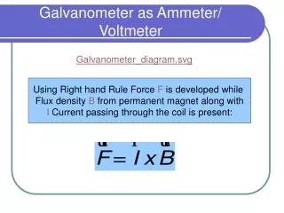
Voltage Comparator • An operational amplifier (Op Amp) can be used as a voltage comparator.
Voltage Comparator • The output voltage (vo) of the Op Amp switches to some positive voltage (less than V+) when the input voltage on the v+ (or INPUT+) pin is greater than the voltage on the v- (or INPUT-) pin. • The output voltage (vo) of the Op Amp switches to some negative voltage (~ V_) when the input voltage on the v+ (or INPUT+) pin is less than the voltage on the v- (or INPUT-) pin.
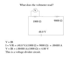
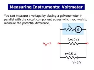
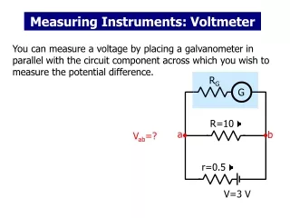
Example: DC Sweep of V2 Output voltage of the LM324 (voltage marker) will change from V- to V+ when V2 equals the voltage at the - input pin (4.5V). LED The light emitting diode (discrete as well as any one of the LEDs in the 10 segment LED display) is modeled as a battery in series with Dbreak. A resistor is needed in series to limit the current to under 10mA.
DC Sweep • Sweep Variable: Voltage Source • Name: V2 • Sweep Type: Linear • Start Value: -9 • End Value: 9 • Increment: 0.1
Nonideal Op Amps • The output voltage of an ideal Op Amp is either V+ (VPOS) or V- (VNEG). • The output voltage of a real Op Amp, such as the LM 324, is not quite 9V (supposed to be 1.5V less than V+). • To measure exactly what the maximum voltage is, disconnect the all components on the output of the LM 324, place a 1-10 kW resistor on the output pin, and apply a volt on the + input terminal that is greater than the voltage on the – input terminal and measure the voltage between the output pin and ground. • Use this voltage when you determine the resistor to use in series with the LED to limit the LED current to 10mA.
LM 324 Quad Op Amp http://www.national.com/ds/LM/LM124.pdf
The Notch The recessed “U” on the DIP (dual inline package) package should be matched with the image when looking down at the package after it has been inserted into the breadboard.
Light Emitting Diode (LED) • A nonlinear component that ‘looks’ like a battery when it is on and an open when it is off. BE CAREFUL: The 10 segment LED array is more sensitive than the discrete LEDs.
10 Segment LED Bar • A LED is located between pairs of pins. Side view Top view
Anode vs. Cathode • Switch your DMM to the diode symbol. • Place the red probe into the V-W plug and the black probe into the COM plug. • Place your probes across the diode. • If the result is a very small number, then your red probe is contacting the anode and the black probe is contacting the cathode of the diode. • If the result is an overload (overflow) condition, then the red probe is contacting the cathode and the black probe is contacting the anode of the diode.
Pre-Lab Report A .pdf file containing: • Calculations of the resistor values used to create a voltage divider that will have node voltages used as the reference signal for the voltage comparator. • The reference signal will be one of the input voltages at the op amp. • A plot of the current through an LED as the voltage of the input of a voltage comparator is varied from -9V to 9V using PSpice. • Select the comparator that is the one that switched the first two LED segments on.
Simulating a LED in PSpice No LED part in the student PSpice so we use a series combination of parts. • Dbreak (diode breakout part) • Allows current to flow when the voltage on the anode is 0.7V higher than the voltage on the cathode. • Vdc • Set to the difference in the voltage needed on the anode to turn the LED on • Our red and green LEDs need between 2-2.5V.
Lab Report • The report should include: • A full schematic of the circuit designed and constructed. • A description of: • The circuit used to regulate the input voltage between -9V and +9V. • This circuit will be used to create the unknown voltage. • The voltage divider used to divide the 9V supply from the ANDY board into the voltage steps described on Slide 3. • The operation of the voltage comparators. • How the current to the LED array and the discrete LEDs was limited. • The circuit used to light the discrete red LED when the unknown voltage is negative. • Includes calculations and PSpice simulations. • Explanation of any discrepancies in the operation of the circuit. • Do not include a validation checksheet mentioned in the manual.
Limitations of Student PSpice • 64 nodes • 20 components • Complex parts, such as some of the Op Amps, count as more than one component. You will not be able to simulate the operation of your entire voltmeter circuit because of these limitations. Break the circuit into subcircuits.
Debugging Your circuit • The best way to determine why your circuit is not functioning as expected is to separate out the subcircuits and verify that they work as designed – i.e., measure node voltages and branch currents and compare them with your calculations and PSpice simulations. • Start at the subcircuits at the beginning of the circuit. • Voltage dividers that are used to define the unknown voltage and the reference voltages for the comparators. • Work your way to the LEDs. • The best way is not to pester the OpEL GTAs until they rebuild your circuit for you. • Reasonable amount of assistance from the GTAs is acceptable. • If you do not know what the voltages should be at certain points of your design, this could impact your validation grade.