Download
1 / 26
290 likes | 700 Vues
Observation of the spin-Hall Effect. 2005. 4. 18 M1 Colloquium in the Frontier Materials Division. Soichiro Sasaki Suzuki-Kusakabe Lab. Graduate School of Engineering Science Osaka University. Abstract.

E N D
Observation of the spin-Hall Effect 2005. 4. 18 M1 Colloquium in the Frontier Materials Division Soichiro Sasaki Suzuki-Kusakabe Lab. Graduate School of Engineering Science Osaka University
Abstract • To realize spin-electronics, techniques to accumulate electron spin in semiconductor devices are required. In the usual spin-electronics devices, spin injection is usually realized using ferromagnets. • The spin-Hall effect is another possibility and we can substitute the effect for ferromagnets. Spin current flows in the direction perpendicular to the direction of charge current when the voltage is applied to an electron system in a semiconductor device. Spin accumulation would occur at two edges as a result. This is called the spin-Hall effect. • The experiments [1,2] I'll introduce succeeded in observation of the spin-Hall effect that was predicted theoretically. Spin accumulation is observed with a Kerr rotation microscope in the first one. Spin-dependence of polarization in a light-emitting diode structure is an evidence in the second one. There are two origins of spin-Hall effect, extrinsic spin-Hall effect and intrinsic spin-Hall effect. The former experiment shows domination in the extrinsic spin-Hall effect. The latter claims observation of intrinsic one. References [1] Y.K. Kato, et al., Science 306 (2004) 1910. [2] J.Wunderlich,Phy. Rev. Lett. Vol.94 (2005) 047204
Contents • Introduction • Observation of the spin-Hall Effect 2.1 Kato’s spin-Hall device 2.2 Wunderlich’s spin-Hall device • Summary
1-1 Spin-electronics devices Spin-FET GMR device Gate bias (Off) Gate electrode Drain (FM) Source (FM) Spin-FET by Datta & Das Current flows Current flows TMR device Channel Gate bias (On) Electrode (Ferromagnel) Insulator (Oxides) No current flows Electrode (Ferromagnet) These devices are realized by using ferromagnets.
Problems of these devices • We use ferromagnets to fabricate spin-electronic devices. However, it is troublesome to fabricate ferromagnets in semiconductor devices. • We must use magnetic field to change the direction of a magnetic moment. We can’t make a device structure, which is controllable by applied magnetic field, smaller than a predicted limit. Spin-Hall effect Solution
1-2 semiconductor hetero junction (a) (b) Heterojunction may used as a n-type device. The electronic system at the interface in AlGaAs/ GaAs junction produces the two-dimensoinal hole gas (The 2DHG), when the bias is introduced as shown by the black lines. Ordinal heterojunction to realize the two-dimensional electron gas. (The 2DEG) 2DEG 2DHG
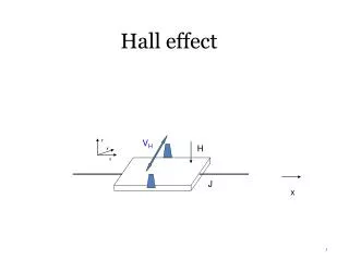
1-3 The Hall effect (Carriers are electrons) Hall voltage ; Lorentz force ; Applied current ; Induced voltage ; (Hall voltage) Density of carriers ; The elementary electric charge ; Velocity of a carrier ;
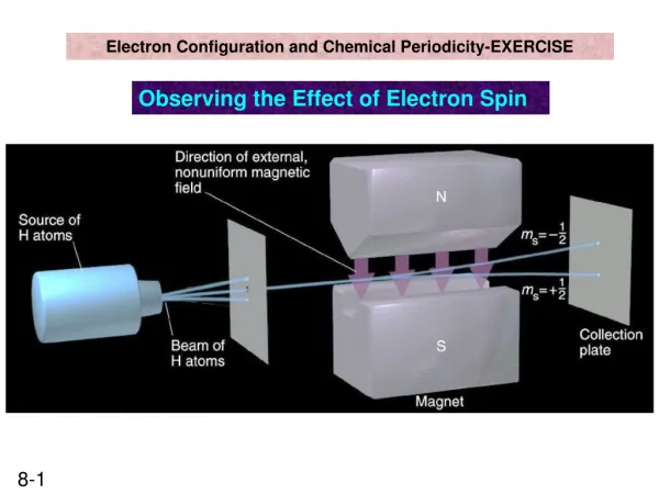
1-4 Spin Hall Effect In a nonmagnetic metal, the spin-orbit interaction causes a pure spin current perpendicular to the applied electric field. the vector of spin- current whose spin is polarized along z axis. Motion of up-spins Spin accumulation Motion of down-spins
Extrinsic Spin-Hall effect • This effect is caused by spin-orbit interaction of impurities. A phenomenological continuous equation of spin density and spin-flux density. Spin relaxation qab : Spin flux density Magnetic field effect Ω=mBgH/h Sb : The spin density H: Magnetic field
Intrinsic Spin-Hall effect • The electrons at the valence band top, i.e. the holes follow an equation of motion in the k-space, in which a band-touching point the acts as a Dirac magnetic monopole in the momentum space. • Valence band top of GaAs is a typical example. Thus p-type doped semiconductor is required to have intrinsic SHE.
1-5 Hall effect v.s. Spin-Hall effect Spin-Hall effect
1-6 Kerr rotational microscopy • When incident linearly polarized light (i) interacts with a magnetic system the reflected light (r) turns out to be elliptically polarized (the orientation of the magnetization M is perpendicular to the surface). Kerr effect Magnetic substance
Kerr rotational microscope Kerr rotaional microscopy (in the Santa Barbara) Schematic of the experimental geometry Phys. Today Vol. 58 Nov.2 17 (Feb. 2005)
Observations of spin-Hall effect • Y. K. Kato, R. C. Myers, A. C. Gossard, D. D. Aschalom, Science Vol.306,1910 (2004);published online 11 November 2004 (10.1126/science.1105514). • J. Wunderlich, B. Kaestner, J. Sinova, T.Jungwirth, Phys. Rev. Lett. Vol. 94,047204 (2005).
2.1 Y. K. Kato’ s experiment Method of detection ; Kerr rotational microscopy Strong point ; It can observe spatial map of spin. Weak point ; The limit of detected spot (more than 1.1μm) Long spin life time is needed to observe the spin-Hall effect.
Kerr rotation in an unstrained sample Kerr rotation, peak KR, and a spin lifetime as a function of x or Bext KR, peak KR, and a spin lifetime as a function of x, Bext & E Schematics of the unstrained GaAs sample
Spin accumulation • Figure A: Two-dimensional images of spin density ns. • Figure B: Two-dimensional images of reflectivity. • These pictures are direct observation of the spin-Hall effect.
Hanle effect of unstrained sample Larmor precession frequency; Electron spin lifetime; Electron g factor; Bohr magneton; The peak Kerr rotation;
Kerr rotation in strained sample Kerr rotation, peak KR, Bint and R as a function of x or Bext Schematics of the strained InxGa1-xAs sample
Hanle effect of strained sample Kerr rotation ; Kerr rotation peak ; Precession frequency; The spin polarization is maximum At when cancels out .
Result of Y. K. Kato’ s experiment • The band structure that is the origin of intrinsic one is broken by straining of the sample. This experiment is caused, they think, by extrinsic one. • If the effect originated in the lattice, then it should depend on the strain direction.
2.2. J. Wunderlich’s experiment Method of detection ; Electroluminescence of LED Strong point ; It can detect magnetic field at very small spot. The crystal used at this experiment is very clean crystal. It has possibility of intrinsic spin-Hall effect. Weak pint ; It can’t detect spatial map of spin .
p-n junction LED device Conduction and valence band profiles Schematic cross section of the device
Schematic of sample and data SEM image of the SHE LED device b: Polarization along z axis measured with active LED 1. c: Polarization with fixed Ip for LED 1 or LED 2.
Result of J. Wunderlich’s experiment • Hitach researchers believe their experiment to be too low in signal to account for the polarization they observed. The spin-Hall effect in their sample is, they believe,intrinsic in origin.
Summary • Using the Kerr rotational microscope, the extrinsic Spin-Hall effect was observed in a n-GaAs thin layer. (Kato’s experiment) • In a strained InGaAs device, no clear evidence of the strain effect on the Spin-Hall effect was observed. Thus, the intrinsic Spin-Hall effect is not observed in this sample. (Kato’s experiment) • Using electrolumimescemce from LED made of 2DHG/2DEG junction, spin polarization is found, which depends on direction of the electric field across 2DHG. This result suggest the intrinsic Spin-Hall effect. (Wunderlich’s experiment)