Download

1 / 74

E N D
0 Welcome. In navigating through the slides, you should click on the left mouse button when (1), you see the mouse holding an x-ray tubehead (see below), (2) you are directed to “click” for the next action and (3) you are done reading a slide. Hitting “Enter” or “Page Down” will also work. To go back to the previous slide, hit “backspace” or “page up”.
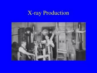
0 X-ray Production The following slides identify atomic structure, the forces at work inside the atom, types of electromagnetic radiation (including x-rays), x-ray characteristics, components of an x-ray machine and x-ray tube, how x-rays are formed and ways to modify the x-ray beam.
Atomic Structure 0 An atom is composed of electrons (with a negative charge), protons (with a positive charge) and neutrons (no charge). The protons and neutrons are found in the nucleus of the atom and the electrons rotate (orbit) around the nucleus. The number of electrons equals the number of protons in an atom so that the atom has no net charge (electrically neutral). Different materials (for example, gold and lead) will have different numbers of protons/electrons in their atoms. However, all the atoms in a given material will have the same number of electrons and protons. (See diagram next slide)
Atom This atom has 7 protons and 7 neutrons in the nucleus. There are 7 electrons orbiting around the nucleus. 0 protons neutrons electrons
0 The electrons are maintained in their orbits around the nucleus by two opposing forces. The first of these, known as electrostatic force, is the attraction between the negative electrons and the positive protons. This attraction causes the electrons to be pulled toward the protons in the nucleus. In order to keep the electrons from dropping into the nucleus, the other force, known as centrifugal force, pulls the electrons away. The balance between these two forces keeps the electrons in orbit. (See next three slides)
0 Electrostatic force is the attraction between the positive protons and negative electrons. Electrons in the orbit closest to the nucleus (the K-shell) will have a greater electrostatic force than will electrons in orbits further from the nucleus. Another term often used is binding energy; this basically represents the amount of energy required to overcome the electrostatic force to remove an electron from its orbit. For our purposes, electrostatic force and binding energy are the same.
0 Centrifugal force pulls the electrons away from the nucleus
0 EF CF The balance between electrostatic force and centrifugal force keeps the electrons in orbit around the nucleus
0 Electromagnetic Radiation An x-ray is one type of electromagnetic radiation. Electromagnetic radiation represents the movement of energy through space as a combination of electric and magnetic fields. All types of electromagnetic radiation, which also includes radiowaves, tv waves, visible light, microwaves and gamma rays, travel at the speed of light (186,000 miles per second). They travel through space in wave form.
W 0 F = 3 W F = 2 D The waves of electromagnetic radiation have two basic properties: wavelength and frequency. The wavelength (W) is the distance from the crest of one wave to the crest of the next wave. The frequency (F) is the number of waves in a given distance (D). If the distance between waves decreases (W becomes shorter), the frequency will increase. The top wave above has a shorter wavelength and a higher frequency than the wave below it.
0 radio waves tv waves visible light x-rays gamma rays cosmic rays Which of the above examples of electromagnetic radiation has the shortest wavelength? Which of the above has the lowest frequency? Cosmic rays Radio waves
0 X-ray Energy The energy of a wave of electromagnetic radiation represents the ability to penetrate an object. The higher the energy, the more easily the wave will pass through the object. The shorter the wavelength, the greater the energy will be and the higher the frequency, the greater the energy will be.
0 A B C Which of the above x-rays has the highest energy? A: It has the shortest wavelength, highest frequency
X-ray Characteristics 0 X-rays have several characteristics, some of which have already been discussed. They are high energy waves, with very short wavelengths, and travel at the speed of light. X-rays have no mass (weight) and no charge (neutral). You cannot see x-rays; they are invisible. X-rays travel in straight lines; they can not curve around a corner. An x-ray beam cannot be focused to a point; the x-ray beam diverges (spreads out) as it travels toward and through the patient. This is similar to a flashlight beam.
X-ray Characteristics (continued) 0 X-rays are differentially absorbed by the materials they pass through. More dense materials (like an amalgam restoration) will absorb more x-rays than less dense material (like skin tissue). This characteristic allows us to see images on an x-ray film. X-rays will cause certain materials to fluoresce (give off light). We use this property with intensifying screens used in extraoral radiography. X-rays can be harmful to living tissue. Because of this, you must keep the number of films taken to the minimum number needed to make a proper diagnosis.
X-ray Equipment 0 2 1 3 X-ray equipment has three basic components: (1) the x-ray tubehead, which produces the x-rays, (2) support arms, which allow you to move the tubehead around the patient’s head and (3) the control panel, which allows you to alter the duration of the x-ray beam (exposure time) and, on some x-ray machines, the intensity (energy) of the x-ray beam.
X-ray Tubehead 0 PID (cone) degrees The x-ray tubehead is attached to the support arms so that it can rotate up and down (vertically;measured in degrees) and sideways (horizontally) to facilitate proper alignment of the x-ray beam. The PID (Position Indicating Device) is attached to the x-ray tubehead where the x-ray beam exits and it identifies the location of the x-ray beam. Some people refer to the PID as a “cone”; the PID’s on very old x-ray machines used to be coneshaped.
mA control 0 exposure time kVp control The control panel, like the one above left, allows you to change exposure time but nothing else. Some machines, like the one above right, have controls for changing the mA and kVp settings in addition to exposure time. The individual controls will be discussed more later.
0 X-ray Tube X-rays are produced in the x-ray tube, which is located in the x-ray tubehead. X-rays are generated when electrons from the filament cross the tube and interact with the target. The two main components of the x-ray tube are the cathode and the anode.
Cathode 0 Focusing cup Filament (tungsten) side view (cross-section) front view (facing target) The cathode is composed of a tungsten filament which is centered in a focusing cup. Electrons are produced by the filament (see next slide) and are focused on the target of the anode where the x-rays are produced. The focusing cup has a negative charge, like the electrons, and this helps direct the electrons to the target (“focuses” them. Electrons can be focused; x-rays cannot).
x-section of filament hot filament electrons Thermionic Emission 0 When you depress the exposure button, electricity flows through the filament in the cathode, causing it to get hot. The hot filament then releases electrons which surround the filament (thermionic emission). The hotter the filament gets, the greater the number of electrons that are released. (Click to depress exposure button and heat filament).
0 side view front view Anode Target Target Copper stem The anode in the x-ray tube is composed of a tungsten target embedded in a copper stem. When electrons from the filament enter the target and generate x-rays, a lot of heat is produced. The copper helps to take some of the heat away from the target so that it doesn’t get too hot.
X-ray Tube Components 0 4 6 3 5 2 7 1 8 9 1. focusing cup 6. copper stem 2. filament 7. leaded glass 3. electron stream 8. x-rays 4. vacuum 9. beryllium window 5. target (for description, see next slide)
X-ray Tube Components (continued) 0 1. Focusing cup: focuses electrons on target 2. Filament: releases electrons when heated 3. Electron stream: electrons cross from filament to target during length of exposure 4. Vacuum: no air or gases inside x-ray tube that might interact with electrons crossing tube 5. Target: x-rays produced when electrons strike target 6. Copper stem: helps remove heat from target 7. Leaded glass: Keeps x-rays from exiting tube in wrong direction 8. X-rays produced in target are emitted in all directions 9. Beryllium window: this non-leaded glass allows x-rays to pass through. The PID would be located directly in line with this window.
0 Photo of an X-ray Tube Leaded glass Beryllium Window Focusing cup (filament located inside) Target
0 X-ray Machine Components X-ray Tubehead Control Panel 110, 220 line Timer Exposure switch mA selector kVp selector Autotransformer Step-down transformer Step-up transformer X-ray Tube Wires Oil
X-ray Machine Voltage 0 The x-ray machine is plugged into a 110-volt outlet (most machines) or a 220-volt outlet (some extraoral machines). The current flowing from these outlets is 60-cycle alternating current. Each cycle is composed of a positive and negative phase. X-rays are only produced during the positive phase; the target needs to be positive to attract the negative electrons from the filament. During the positive portion of the cycle, the voltage starts out at zero and climbs to the maximum voltage before dropping back down to zero and entering the negative phase. Each complete cycle lasts 1/60 of a second; there are 60 cycles per second. (See next slide)
voltage starts at zero and reaches a maximum of 110 or 220 before going back to zero 0 + 110, 220 positive 0 - 110, 220 negative target positive; electrons flow target positive; electrons flow target negative; no electron flow
0 Many machines now convert the alternating current into a direct current (constant potential). Instead of cycles going from zero to the maximum, both positive and negative, the voltage stays at the maximum positive value, creating more effective x-ray production. This allows for shorter exposure times. 60-cycle Alternating Current Direct Current (Constant Potential)
Timer 0 The timer controls the length of the exposure. The black numbers above represent impulses. The red numbers are seconds.
With alternating current, there are 60 complete cycles each second; each cycle represents an impulse and is 1/60 of a second. To change impulses into seconds, divide the number of impulses by 60. To convert seconds to impulses, multiply by 60. 0 1/60 sec. Number of Impulses = seconds 60 Number of seconds X 60 = impulses 60 impulses/60 = 1 second 30 impulses/60 = 0.5 (1/2) second 15 impulses/60 = 0.25 (1/4) second 0.75 (3/4) second X 60 = 45 impulses 0.1 (1/10) second X 60 = 6 impulses
0 There are two electrical circuits operating during an x-ray exposure. The first of these is the low-voltage circuit that controls the heating of the filament. When the exposure button is depressed, this low voltage circuit operates for ½ second or less to heat up the filament. There are no x-rays produced during this time. As you continue to depress the exposure button, the high-voltage circuit is activated. This circuit controls the flow of electrons across the x-ray tube; during the positive portion of the alternating current cycle, the negative electrons are pulled across the x-ray tube to the positive target. X-rays are produced until the exposure time ends. The length of time the high-voltage circuit is operating represents the exposure time. (See next slide).
0 X-ray Exposure 1. Depress exposure button 2. Activate low-voltage circuit to heat filament 3. Activate high-voltage circuit to pull electrons across tube 5. X-ray production stops when exposure time ends. Release exposure button 4. Electrons cross tube, strike target and produce x-rays
0 Exposure Button The timer determines the length of the exposure, not how long you hold down the exposure button; you cannot overexpose by holding the exposure button down for an extended period. However, you can underexpose by releasing the exposure button too soon; the exposure terminates as soon as you release the button.
milliAmpere (mA) selector 0 mA setting The mA (milliAmpere) setting determines the amount of current that will flow through the filament in the cathode. This filament is very thin; it doesn’t take much current (voltage) to make it very hot. The higher the mA setting, the higher the filament temperature and the greater the number of electrons that are produced.
Step-Down Transformer 0 If the voltage flowing through the filament is too high, the filament will burn up. In order to reduce the voltage, the current flows through a step-down transformer before reaching the filament. The voltage reaching the step-down transformer is determined by the mA setting. The step-down transformer reduces the incoming voltage to about 10 volts, which results in a current of 4-5 amps flowing through the filament.
Step-Down Transformer 110 volts or less current flow 10 volts current flow 0 The current enters the step-down transformer on the primary (input) side and exits on the secondary (output) side. The fewer turns in the coil on the secondary side, the lower the output voltage will be. The primary coil below would have 110 turns, the secondary coil would have 10. (Each loop of the coil is a “turn”; the number of turns in the diagram below has been reduced for easier viewing). Primary Secondary
kiloVolt peak (kVp) control 0 kVp readout kVp control knob The kVp control regulates the voltage across the x-ray tube. (A kilovolt represents 1000 volts; 70 kV equals 70,000 volts. A 70 kVp setting means the peak, or maximum voltage, is 70,000 volts). The higher the voltage, the faster the electrons will travel from the filament to the target. The kVp control knob regulates the autotransformer (see next slide).
Autotransformer 0 The autotransformer determines how much voltage will go to the step-up transformer. Basically, a transformer is a series of wire coils. In the autotransformer, the more turns of the coil that are selected (using the kVp control knob), the higher the voltage across the x-ray tube will be. This is similar to the function of a rheostat. The following slide shows how this works. The incoming line voltage will be 110 volts. The exiting voltage will be 65 volts if the kVp control is set at 65. The exiting voltage will be 80 volts if the kVp setting is 80.
Autotransformer: if the setting is changed to 80, 80 volts leave the autotransformer. Autotransformer: the initial setting is 65; 65 volts leave the autotransformer. 0 110 V current flow kVp selector 65 volts 80 volts to step-up transformer
0 Step-Up Transformer The voltage coming from the autotransformer next passes through the step-up transformer, where it is dramatically increased. The ultimate voltage coming from the step-up transformer is roughly a thousand times more than the entering voltage. For example, if you set the kVp control knob to 65, 65 volts will exit the autotransformer. This 65 volts is increased to 65,000 volts by the step-up transformer. (The “k” in kVp stands for one thousand; 65 kV is 65,000 volts). The side of the step-up transformer where the voltage enters (primary side) has far fewer turns in the coil than the exit (secondary) side.
65-90 volts current flow 65,000 to 90,000 volts current flow Step-Up Transformer 0 The current enters the step-down transformer on the primary (input) side and exits on the secondary (output) side. The more turns in the coil on the secondary side, the higher the output voltage will be. The secondary coil in the step-up transformer has 1000 times as many turns as the primary coil. (Again, the number of turns has been reduced for easier viewing). Primary Secondary
kVp filament The relationship of the various x-ray machine components are shown in the diagram below. They form the high-voltage and low-voltage circuits. For a more detailed review of the components, see next slide. 0 110 volts 10 volts 65,000 to 90,000 volts
While keeping the exposure button depressed, the high-voltage circuit is activated to pull the electrons from the filament to the target, producing x-rays. (Click to produce x-rays). exposure button The x-rays pass through the filter and collimator before exiting through the PID. (Click for next slide) When the exposure button is depressed, the current can flow into the x-ray tubehead. This activates the low-voltage circuit which heats the filament; this lasts for ½ second (Click to depress exposure button). The length of the exposure is selected with the timer. The x-ray machine is plugged into the electrical outlet (110 volts usually). 0 oil filament filter
Step-up Trans oil barrier material Step-down Trans The tubehead is filled with oil which surrounds the transformers, x-ray tube and electrical wires. The primary function of the oil is to insulate the electrical components. It also helps to cool the anode and, as we will discuss later, it helps in filtration of the x-ray beam. The barrier material prevents the oil from leaking out of the tubehead but still allows most x-rays to pass through. 0
0 X-ray Production There are two types of x-rays produced in the target of the x-ray tube. The majority are called Bremmstrahlung radiation and the others are called Characteristic radiation.
Bremsstrahlung Radiation 0 (Also known as braking radiation or general radiation) Bremmstrahlung x-rays are produced when high-speed electrons from the filament are slowed down as they pass close to, or strike, the nuclei of the target atoms. The closer the electrons are to the nucleus, the more they will be slowed down. The higher the speed of the electrons crossing the target, the higher the average energy of the x-rays produced. The electrons may interact with several target atoms before losing all of their energy.
0 Bremsstrahlung X-ray Production Electron slowed down by positive charge of nucelus; energy released in form of x-ray + High-speed electron from filament enters tungsten atom Electron continues on in different direction to interact with other atoms until all of its energy is lost
Bremsstrahlung X-ray Production Maximum energy 0 + High-speed electron from filament enters tungsten atom and strikes target, losing all its energy and disappearing The x-ray produced has energy equal to the energy of the high-speed electron; this is the maximum energy possible
0 Characteristic Radiation Characteristic x-rays are produced when a high-speed electron from the filament collides with an electron in one of the orbits of a target atom; the electron is knocked out of its orbit, creating a void (open space). This space is immediately filled by an electron from an outer orbit. When the electron drops into the open space, energy is released in the form of a characteristic x-ray. The energy of the high-speed electron must be higher than the binding energy of the target electron with which it interacts in order to eject the target electron. Both electrons leave the atom.