Download
1 / 8
80 likes | 208 Vues
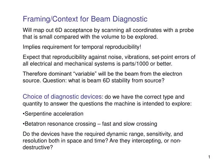
Framing/Context for Beam Diagnostic Will map out 6D acceptance by scanning all coordinates with a probe that is small compared with the volume to be explored. Implies requirement for temporal reproducibility!

E N D
Framing/Context for Beam Diagnostic Will map out 6D acceptance by scanning all coordinates with a probe that is small compared with the volume to be explored. Implies requirement for temporal reproducibility! Expect that reproducibility against noise, vibrations, set-point errors of all electrical and mechanical systems is parts/1000 or better. Therefore dominant “variable” will be the beam from the electron source. Question: what is beam 6D stability from source? • Choice of diagnostic devices: do we have the correct type and quantity to answer the questions the machine is intended to explore: • Serpentine acceleration • Betatron resonance crossing – fast and slow crossing • Do the devices have the required dynamic range, sensitivity, and resolution both in space and time? Are they intercepting, or non-destructive?
Beam Transmission Current transformers or Faraday cups in injection/extraction lines Resistive wall monitor in ring (turn by turn) Longitudinal dynamics Measure: profile, and centroid (phase and energy) Instrumentation/phase & profile: w/b resistive wall-current monitor in ring. If band-width is inadequate for profile, use transverse deflecting mode cavity in extraction line? Instrumentation/momentum: spectrometer in injection/extraction lines AND BPMs in ring to measure/calibrate CO vs momentum. Requirement to scan in momentum and phase implies desired variability of ERLP extraction energy – AND sophisticated RF synchronization system
Phase Synchronization Desire a phase match (and/or incrementable offset) at time of transfer of single bunch – with two possibly different frequencies in ERLP & EMMA Phase comparison/control of different frequencies (ω1 and ω2) difficult because of rapidly changing (MHz) saw-tooth signal if frequency difference is large. Standard technique “heterodyne” is to artificially synthesize a Δω=(ω1- ω2) mix it with actual ω2 and then compare with actual ω1. The output signal will now be slowly changing, and can form the basis of a control loop. Even better, with modern DDS, one can choose the phase-integral of Δω during the lock-in to be an exact number of wavelengths, so that by the end of lock-in ω1 and ω2 are in a definite, desired phase relation at the moment that beam is transferred. And, of course, this can be incremented. Question of which machine is “master” and “slave”, may need some attention, particularly if beam delivered from ERLP changes as the ERLP frequency is varied.
BPMs (called PUEs at BNL) The most crucial piece of instrumentation. Use electrostatic button-type devices. Induced signal is proportional to fraction of E-field lines intercepted by button, so scales with button area. Measures: closed orbit, lattice functions, betatron oscillations as sampled at discrete locations. Needs: single-turn time resolution, and many-turn acquisition/storage. Dynamic range: no an issue, will always work with 1-2 E8 electrons. BUT sensitivity/resolution is strong issue. E10/bunch => resolution 10 μm E9 20 E8 50 E7 >100 μm Numbers are “illustrative”, will depend on technology used
Resonance Crossing (RC) • Try to find its effect on “emittance”. • In fact, there are two-types of emittance, and both are relevant to this issue. • Intrinsic emittance: 3 π mm.mrad • Swept-out emittance: up to 3 π m.mrad (A possible corollary of emittance growth is beam loss, so there may also be some information coming from beam current transmission/loss monitors.) • Concept of this study has changed dramatically since 2004. • Originally imagined to explore effect of RC by monitoring increase of an initially large intrinsic emittance. • However, now have a small probe emittance which is used to investigate effect of RC on the swept-out emittance. Issues: wish to monitor both the emittance of the probe AND the emittance swept out as input centroid is scanned in x,x’ etc. But cannot measure emittance directly – only the projections on x. Reconstruction of x’ difficult because Twiss α,β,γ vary from cell to cell and turn-to-turn.
Swept-out Emittance Measurement device: all ring BPMs, and reconstruction of x’ from reconstruction of α,β,γ. (“Large” amounts of data to be acquired and processed to achieve this.) Depends on ability to scan centroid in x,x’ – so flexibility of injection system is crucial. Do we want extra BPMs or an OTR near septum & kickers? Swept-out emittance is immune to the direct space-charge resonances (e.g. ¼-integer in Machida’s simulation) – good. However, it is not immune to image-forces – Shinji claims these are weak for small amplitudes, but what about large amplitude? Question: can we do slow crossing? Answer: yes if slow means 100 turns, but not 1000 turns.
Intrinsic Emittance Monitoring emittance of the probe (pencil beam). Will make measurements in the injection/extraction lines, and in the ring. In the ring, an ISSUE is “whether we have separated turns” during accceleration – implications for probe size. Reconstruction is based on 3 measurements at different phase advance – will be non trivial: α,β,γ. But in inject/extract lines “classic” emittance measurement rig is easy – provided enough spatial resolution. What devices are possible/appropriate? Basically choice between screens (e.g. OTR, YAG) and scanning wire. List “pros and cons”. • Screens • Get all the information in “one shot” – good/important when reproducibility is low. • Typically poor dynamic range (e.g. resolve halo vs core). • Degrade all turns, not just the one being measured. • Might be useful immediately after injection “to find the beam”.
Wire Scanner • Have to wait many pulses to build up transverse profile – therefore reproducibility against beam jitter is crucial. • Interesting acquisition/synchronization problem: have to acquire signal while beam is there, for a very short time (few tens ps) between 20 Hz cycles. • Dynamic range: good. • Resolution: good if you are willing to wait long enough for small steps. • Damage only the turn being measured – not previous turns (assuming separated). Issue: resolution. Inside the ring, smallest beam width is 0.3mm. Resolving sub-structure will be difficult for wire or OTR. This makes questionable their use in the ring. For the case of the wire: will have to find the beam with BPMs before using the wire. Wire drive and its position encoder must be capable of 25 micron steps. Depending on wire thickness, it may behave more like a “blade” scanner. Conclusion/guess Wires preferred for ring IFF data acquisition/synchronization is not difficult issue. Injection/extraction “emittance” rig: devices as local experts prefer (e.g. harps, OTR, wire, etc). Beamline optics: need large enough beta function to make easy high resolution measurements of transverse profiles (H and V).