Download
1 / 18
180 likes | 185 Vues
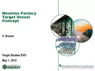
Investigation of a “Pencil Shaped” Solid Target. Peter Loveridge, Mike Fitton, Ottone Caretta High Power Targets Group Rutherford Appleton Laboratory, UK P.Loveridge@rl.ac.uk January 2011. 1. Introduction. Beam Separator. 4 MW Proton beam from accumulator at 50 Hz. Decay Volume.

E N D
Investigation of a “Pencil Shaped” Solid Target Peter Loveridge, Mike Fitton, Ottone Caretta High Power Targets Group Rutherford Appleton Laboratory, UK P.Loveridge@rl.ac.uk January 2011 1
Introduction Beam Separator 4 MW Proton beam from accumulator at 50 Hz Decay Volume 4 x 1MW Proton beam each at 12.5 Hz Target Station (4 targets, 4 horns) • EUROnu target-station scheme has 4 targets and 4 horns • Each target exposed to ¼ of the total beam power (1.11e14 protons/pulse, 4.5 GeV, 12.5 Hz repetition rate) • Reduced Beam induced heating in target by a factor of 4 • Baseline target technology is a solid beryllium rod, peripherally cooled 2 EUROnu Annual Meeting, January 2011
Beryllium Material Properties 3 EUROnu Annual Meeting, January 2011
Beryllium Material Properties Note degradation in strength at elevated temperature Suggest to limit Tmax to, say ~300°C ? Need to define a design stress limit as some fraction of σy say, ~160 MPa ? 4 EUROnu Annual Meeting, January 2011
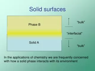
Motivation for a “Pencil shaped” target • Need to find a way to reduce the high steady-state thermal stress present in the case of a solid cylindrical beryllium target • Stress driven by large radial temperature variation at thermal equilibrium • A potential solution – place the cooling fluid closer to the region peak energy deposition in the target • Shorter conduction path • Reduced ΔT between surface and location of Tmax • Tmax is reduced – more favourable material properties • Lower thermal stress • Engineering solutions being considered: • “Pencil shaped” solid target - PL • Packed pebble bed target - TD 5 EUROnu Annual Meeting, January 2011
“Pencil” Target Concept Design • Pencil shaped Beryllium target contained within a Titanium “can” • Pressurised Helium gas cooling, outlet at 10 bar • Supported as a cantilever from the upstream end He In He Out Titanium “Can” Beryllium Target BEAM Beam Window Intermediate tube Drawing not to scale! 6 EUROnu Annual Meeting, January 2011
Geometry Parameterisation Length 800 mm B C A Ø24 mm (r = 3σ) Beam Cylinder “Pencil” Cone Deposited beam energy in three example beryllium targets 7 EUROnu Annual Meeting, January 2011
Deposited Energy (FLUKA) • Benefits of a cone shape (compared to a cylinder): • Integrated heat load is reduced (less material in front of the beam?) • Coolant fluid in close proximity to the region of maximum heat deposition Cylinder: Ø24 mm, 800 mm long Integrated Heat Load 2.9 kJ/pulse i.e. 36 kW heating from 1 MW beam Cone: 1 mm < Ø < 24 mm, 800 mm long Integrated Heat Load 2.0 kJ/pulse i.e. 24 kW heating from 1 MW beam 8 EUROnu Annual Meeting, January 2011
Well Centred Beam (Standard Operating Case) • Results from steady-state thermo-mechanical analysis: • Need surface HTC of the order 4kW/m2K in order to limit Tmax to ~300°C • Gives max stress = 83 MPa Uniform HTC = 4kW/m2K 72°C 318°C 0MPa 83MPa Temperature (left) and Von-Mises thermal stress (right) corresponding to a steady state operation with a surface HTC = 4kW/m2K, bulk fluid temp = 30°C 9 EUROnu Annual Meeting, January 2011
Off Centre Beam (Accident Case) • Results from steady-state thermo-mechanical analysis: • Total heat load is reduced in the case of the beam being mis-steered • Location of Tmax moves downstream Uniform HTC = 4kW/m2K Lateral beam position offset = 2 x beam sigma: Integrated Heat Load 21.2 kJ/pulse i.e. 14 kW heating from 1 MW beam 34°C 201°C Energy deposition (left) and temperature corresponding to a steady state operation with a surface HTC = 4kW/m2K, bulk fluid temp = 30°C (right) 10 EUROnu Annual Meeting, January 2011
Off Centre Beam (Accident Case) • Lateral deflection due to steady-state off-centre heating: • 13 mm lateral deflection if cantilevered from downstream end • Max stress increased to 120 MPa (recall 83 MPa in well centred beam case) 0 mm 13 mm 0MPa 120MPa Deflection (left) and Von-Mises thermal stress (right) corresponding to a laterally mis-steered beam 11 EUROnu Annual Meeting, January 2011
CFX conjugate heat transfer model • Cooling fluid = Helium • Turbulence model = Shear Stress Transport (SST) • Inlet mass flow rate = 60g/s • Inlet temperature = 300K • Outlet Pressure = 10bar • Heat deposition in target = 24kW steady state from Fluka simulation • Model of 36° slice (1/10th of target) with symmetry boundary conditions • Cooling channel outer surface defined by 3 radii and connected with spline Outlet Inlet Helium Target Radius 1 Radius 2 Radius 3 0.4m 0.4m 12 EUROnu Annual Meeting, January 2011
Mesh at downstream end of target Fluid Domain Boundary layer inflation Solid Domain 13 EUROnu Annual Meeting, January 2011
Linear cooling channel (Equal area at both ends) • Cooling channel • R1 = 7.2mm • R2 = 10.6mm • R3 = 14mm Helium velocity minimum at peak heat 4kW/m2.K Design 1 14 EUROnu Annual Meeting, January 2011
Constant area (at R1, R2 & R3) cooling channel • Cooling channel • R1 = 7.2mm • R2 = 9.5mm • R3 = 14mm Helium velocity maximum here due to gas heating 4kW/m2.K Design 2 15 EUROnu Annual Meeting, January 2011
Cooling channel area reduced at centre & increased at ends (2) • Cooling channel • R1 = 9mm • R2 = 9mm • R3 = 14.4mm Helium velocity maximum at peak heat 4kW/m2.K Design 3 16 EUROnu Annual Meeting, January 2011
Helium Cooling Summary • Beryllium target can be cooled with 60g/s helium at 10bar and maintain a steady-state temperature of approximately 300°C • Mass flow rate is double that of the T2K target cooling but the volume flow rate is a factor of 3 less due to the target operating at high pressure • 60g/s @ 10bar & 300K = 135m3/hr (Design 3 volumetric flow rate) • For comparison 30g/s @ 1.6bar & 300K = 421m3/hr (T2K volumetric flow rate) • Guess total DP (Target + Heat Exchangers + Pipe work) is 5bar • Ideal compressor work is then approximately 8kW (T2K = 20kW) • Seems reasonable 17 EUROnu Annual Meeting, January 2011
General Conclusions and further work • Pencil target geometry merits further investigation • Steady-state thermal stress within acceptable range • Initial investigation into pressurised helium cooling appears feasible • Off centre beam effects could be problematic..? • Need to study pion production for “pencil” target geometry – Andrea?? • Look for any “show-stoppers” • Carry out further thermo-mechanical studies including: • Input CFX heat transfer result into ANSYS mechanical model • Profile the target instead of the “can” for ease of manufacture • Helium return flow 18 EUROnu Annual Meeting, January 2011