Download

1 / 45
480 likes | 1.01k Vues
Industrial Autom ation Automation Industrielle Industrielle Automation 3 Industrial Communication Systems Field bus: standards 3.3 Bus de terrain standard Standard-Feldbusse Prof. Dr. H. Kirrmann ABB Research Center, Baden, Switzerland Field busses: Standard field busses

E N D
Industrial AutomationAutomation IndustrielleIndustrielle Automation 3 Industrial Communication Systems Field bus: standards 3.3 Bus de terrain standard Standard-Feldbusse Prof. Dr. H. Kirrmann ABB Research Center, Baden, Switzerland
Field busses: Standard field busses 3.1 Field bus types Classes Physical layer Networking 3.2 Field bus operation Centralized - Decentralized Cyclic and Event Driven Operation 3.3 Field bus standards International standard(s) HART ASI Interbus-S CAN Profibus LON Ethernet Automotive Busses
Which field bus ? • A-bus • IEEE 1118 • Partnerbus (Bitbus) • Arcnet • Instabus • P-net • Arinc 625 • Interbus-S * • Profibus-FMS * • ASI * • ISA SP50 • Profibus-PA • Batibus • IsiBus • Profibus-DP • Bitbus • IHS • PDV * • CAN • ISP * • SERCOS • ControlNet • J-1708 • SDS • DeviceNet • J-1850 • Sigma-i • DIN V 43322 • LAC • Sinec H1 * • DIN 66348 • LON (Meßbus) • FAIS • Sinec L1 • MAP • EIB • Master FB • Spabus • Ethernet • MB90 • Suconet • Factor • MIL 1553 • VAN • Fieldbus Foundation • MODBUS • WorldFIP • FIP • MVB • ZB10 * • Hart • P13/42 • ... • IEC 61158 • P14
Worldwide most popular field busses Bus User* Application Sponsor CANs 25% Automotive, Process control CiA, OVDA, Honeywell Profibus (3 kinds) 26% Process control Siemens, ABB LON 6% Building systems Echelon, ABB Ethernet 50% Plant bus all Interbus-S 7% Manufacturing Phoenix Contact Fieldbus Foundation, HART 7% Chemical Industry Fisher-Rosemount, ABB ASI 9% Building Systems Siemens Modbus 22% obsolete point-to-point many ControlNet 14% plant bus Rockwell *source: ISA, Jim Pinto (1999) Sum > 100%, since firms support more than one bus European market in 2002: 199 Mio €, 16.6 % increase (Profibus: 1/3 market share) **source: Elektronik, Heft 7 2002
10,000 1000 100 10 10 100 1000 10,000 Different classes of field busses One bus type cannot serve all applications and all device types efficiently... Data Networks Workstations, robots, PCs Higher cost Not bus powered Long messages (e-mail, files) Not intrinsically safe Coax cable, fiber Max distance miles Sensor Bus Simple devices Low cost Bus powered (?) Short messages (bits) Fixed configuration Not intrinsically safe Twisted pair Max distance 500m frame size (bytes) High Speed Fieldbus PLC, DCS, remote I/O, motors $$ Medium cost Non bus powered Messages: values, status Not intrinsically safe Shielded twisted pair Max distance 800m Low Speed Fieldbus Process instruments, valves Medium cost Bus-powered (2 wire) Messages: values, status Intrinsically safe Twisted pair (reuse 4-20 mA) Max distance 1200m source: ABB poll time, milliseconds
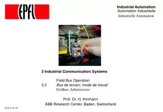
Field device: example differential pressure transducer 4..20 mA current loop fluid The device transmits its value by means of a current loop
4-20 mA loop - the conventional, analog standard (recall) The 4-20 mA is the most common analog transmission standard in industry sensor transducer reader reader voltagesource 10V..24V 1 2 i(t) = f(v) flow R1 R2 R3 RL1 RL2 RL3 RL4 RL4 conductor resistance i(t) = 0, 4..20 mA The transducer limits the current to a value between 4 mA and 20 mA, proportional to the measured value, while 0 mA signals an error (wire break) The voltage drop along the cable and the number of readers induces no error. Simple devices are powered directly by the residual current (4mA), allowing to transmit signal and power through a single pair of wires. Remember: 4-20mA is basically a point-to-point communication (one source)
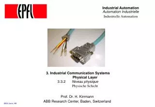
3.3.2 HART Data over 4..20 mA loops
HART - Principle HART (Highway Addressable Remote Transducer) was developed by Fisher-Rosemount to retrofit 4-to-20mA current loop transducers with digital data communication. HART modulates the 4-20mA current with a low-level frequency-shift-keyed (FSK) sine-wave signal, without affecting the average analogue signal. HART uses low frequencies (1200Hz and 2200 Hz) to deal with poor cabling, its rate is 1200 Bd - but sufficient. HART uses Bell 202 modem technology, ADSL technology was not available in 1989, at the time HART was designed Transmission of device characteristics is normally not real-time critical
HART - Protocol Hart communicates point-to-point, under the control of a master, e.g. a hand-held device Master Slave command Indication Request time-out response Response Confirmation Hart frame format (character-oriented): preamble start address command bytecount [status] data data checksum 5..20(xFF) 1 1..5 1 1 [2](slave response) 0..25(recommended) 1
HART - Commands Universal commands (mandatory):identification,primary measured variable and unit (floating point format)loop current value (%) = same info as current loop read current and up to four predefined process variables write short polling addresssensor serial numberinstrument manufacturer, model, tag, serial number, descriptor, range limits, … Common practice (optional)time constants, range,EEPROM control, diagnostics,… total: 44 standard commands, plus user-defined commands Transducer-specific (user-defined)calibration data,trimming,…
HART - Importance Practically all 4..20mA devices come equipped with HART today About 40 Mio devices are sold per year. http://www.hartcomm.org/ more info: http://www.thehartbook.com/default.asp
3.3.3 ASI Small installation bus
D0 = sensor 1 one connection D1 = sensor 2 D2 = actuator 1 AS-InterfaceSlave IC D3 = actuator 2 P0 Watchdog 1 moduleenclosure up to 4 sensorsor/and4 actuators energy ASI (1) - Sensor bus Wiring ASI = Actor-Sensor Interface Very simple sensor bus for building automation, combining power and data on the same wires, transmitting mostly binary signals • mechanically coded flat cable - two wires for data and power • insulation piercing connectors - simple & safe - protection class up to IP67, even after disconnecting • directly connected slaves • - sensors, actuators - valve terminals - electrical modules etc. vampire-connector
ASI (2) - Data sheet • master-slave principle • up to 31 slaves on one line • cycle time < 5 ms • each slave can have up to 4 digital inputs + 4 digital outputs • additional 4 parameter bits / slave • Max. 248 digital Inputs and Outputs • also possible: analogue I/O (but ..) • automatic address numbering via bus connection c o n t r o l l e r m a s t e r master calls T o S l a v e 1 T o S l a v e 2 T o S l a v e 3 1 T o S l a v e 1 S l a v e 1 S l a v e 2 S l a v e 3 1 S l a v e 1 slave response
ASI (3) - Topography • unshielded 2-wire cable • data and power on one cable • extension: 100 m (300 m with extender) • no terminating resistor necessary • free tree structure of network • protection class up to IP67
3.3.4 Interbus-S Discrete Manufacturing bus
Interbus-S (2) - Topology Master optical fibres also available BA remote "bus"(ring) localbus (flat cable) BA 400 m between devices BC IO IO IO 5-wire loop (2 wire, includes power) bus coupler
Interbus-S (4) - Analysis + - • standard in CENELEC • market centered on manufacturing • 1700 products, 270 manufacturers,375.000 applications • limited number of variables (4096 bits) • ring structure sensitive to disruptions • good experience in field wiring(intelligent wiring bar) • sensitive to misplacement • easy to engineer • clumsy and slow message service • easy to program (IEC 61131) • medium user community + far extension (400m .. 13 km) • good response time • few and costly tools • conformance test • strong ties to Phoenix Contact
3.3.5 CAN Automotive bus
CAN (1) - Data Sheet • SupportersAutomotive industry, Intel/Bosch, Honeywell, Allen-Bradley • Standard SAE (automotive), ISO11898 (only drivers), IEC 61158-x (?) • Mediumdominant-recessive (fibre, open collector), ISO 11898 • Medium redundancynone • Connectorunspecified • Distance40m @ 1 Mb/s (A); 400m @ 100kb/s (B); 1000m @ 25kb/s (B) • Repeatersunspecified (useless) • EncodingNRZ, bit stuffing • User bits in frame64 • Mastershipmulti-master, 12-bit bisection, bit-wise arbitration • Mastership redundancy none (use device redundancy) • Link layer controlconnectionless (command/reply/acknowledgement) • Upper layersno transport, no session, implicit presentation • Application ProtocolsCAL, SDS, DeviceNet (profiles) • Chipscomes free with processor (Intel: 82527, 8xC196CA; Philips: 82C200, 8xC592; Motorola: 68HC05X4, 68HC705X32; Siemens: SAB-C167
CAN (2) - Analysis + - ”Unix" of the fieldbus world. • strong market presence, Nr 1 in USA(> 12 Mio chips per year) • limited product distance x rate (40 m x Mbit/s) • sluggish real-time response (2.5 ms) • supported by user organisations ODVA, Honeywell, AB. • non-deterministic medium access • several incompatible application layers (CiA, DeviceNet, SDS) • numerous low cost chips, come free with many embedded controllers • strongly protected by patents (Bosch) • application layer definition • interoperability questionable (too many different implementations) • application layer profiles • bus analyzers and configuration tools available • small data size and limited number of registers in the chips. • no standard message services. • Market: industrial automation, automobiles
3.3.6 Profibus The process bus
Profibus - Family PROFIBUS-DP (Distributed Processing) Designed for communication between programmable logic controllers and decentralized I/O, basically under the control of a single master Replaces parallel signal transmission with 24 V or 0 to 20 mA by “ intelligent DIN rail” PROFIBUS-PA (Process Automation) Permits data communication and power over the bus using 2-wire Connects sensors and actors on one common bus line even in intrinsically-safe areas. (chemical industry) Physical Layer according to international standard IEC 61158-2. PROFIBUS-FMS (Field Messaging Specification) General-purpose for peer-to-peer communication at the cell level. Can be used for extensive and complex communication tasks.Academic approach (layer 7 services based on MMS, ISO 9506). Disappearing
Profibus - Stack FMS DP PA FMS PA-profiles DP-profiles device profiles DP basic functions Fieldbus Messaging Specification Upper layers Link IEC interface RS 485 Fibre optics IEC 61158-2 Phy
Profibus - Data sheet Topography: bus Medium: • TWP @ 31.25 kbits/s (intrinsic safety), 10 devices (PA) • RS 485 @ 19.2 kbit/s.. 500 kbit/s (FMS) • RS 485 or fibres @ 1.5 Mbit/s (12 Mbit/s) (DP) PA: Manchester II, preamble, delimiters Signaling: DP, FMS: UART 11 bit/character Integrity CRC8, HD = 4 Collision none under normal conditions not supported by the controller Medium redundancy Medium Access DP: central master, cyclic polling (see: 3.1.2) FMS, PA: token passing Communication chip dedicated chips for 12 Mbit/s Processor integration can use UART interface on most processors directly depends on number of slaves (cyclic, not periodic) Cycle Time Address space 8 bit device address up to 512 bits in Process Data, 2048 bits in messages Frame size (useful data) Link Layer Services • SDN Send Data with No acknowledgement • SDA Send Data with Acknowledgement • SRD Send and Request Data with reply • CSRD Cyclic Send and Request Data with reply
Profibus - Analysis + - MS-DOS of the fieldbus world Standardized by CENELEC (EN 50 170-3) • Exists in four incompatible versions (FMS, DP, PA, 12 Mbit/s), evolving specifications. Wide support by Siemens(Profibus DP is backbone of Simatic S7) and active Profibus User Organization (PNO) with >1000 companies. • Most products do not implement all the Profibus functionality, interoperability is questionable outside of one manufacturer 200,000 applications, > 2 Mio devices • Additional protocols exist within Siemens Low entry price (originally simple UART protocol at 500 kbit/s with RS 485 drivers) • Weak physical layer (RS 485 at 1,5 Mb/s);to remedy this, a 12 Mb/s version has been developed (does not significantly improve response time, but limits distance). Several implementations based on most commons processors and micro controllers (8051, NEC V25, 80186, 68302). Development tools available (Softing, I-tec). • Complex configuration - all connections must be set up beforehand (except network management): tools required. Extended Application Layer (FMS) and Network Management (SM7, SM2) • Little used outside of Europe (identified in USA / Asia with Siemens/Germany ) Market: industry automation
3.3.7 LonWorks The building automation bus
LON (1) - Data sheet Topography: bus Medium: STP 150 Ohm @ 1.25 Mbit/s 300m, transformer-coupling UTP 100 Ohm, @ 78 kbit/s, 1300m, transformer-coupling reduced to 100m with free topology power line carrier @ 9.6 kbit/s, limited by -55dB radio @ 4.9 kbit/s Communication chip Neuron chip (Motorola, Hitachi) none Medium redundancy: Differential Manchester for STP, UTP Signalling: p-persistent CSMA/CD Medium access: 3 ms (single call/reply), 400 exchanges/s @ 1.25 Mbit/s Response Time 32385 stations Address space up to 1824 bits Frame size (useful data) Integrity CRC16, HD = 2 against steps, =1 against sync slips) full 7-layer stack Higher-level protocols programmed in Neuron-C Application LONMark group (www.echelon.com) Support
LON (2) - Stack Application network variable exchange, network management application-specific RPC, etc.. Session Layer request-response Transport Layer acknowledged and unacknowledged, unicast and multicast Authentication server Transaction Control Sublayer common ordering and duplicate detection Network Layer connectionless, domain-wide broadcast, no segmentation, loop-free topology, learning routers Link Layer connectionless frame transfer, framing, data encoding, CRC error detection MAC sublayer predictive p-persistent CSMA: collision avoidance; optional priority and collision detection Physical Layer multiple-media, medium-specific protocols (e.g. spread-spectrum)
LON (3) - Analysis + "Macintosh" of the fieldbus world - • several media, products, protocols, networking, support, starter kits, tools and documentation. • sluggish response time: > 7ms per variable. • cannot be used in a fast control loop such as drives or substation protection. • easy, plug-and-play access. • low chip costs (10$), but a LON subprint costs about 500$. • non-deterministic medium access (p-persistent CSMA) • only fieldbus in industry (except for IEC's TCN) which supports interoperability of networks of different speeds. • low data integrity due to the use of differential manchester encoding and lack of frame delimiter / size field. • only fieldbus to provide authentication. • standard network variable types definition (SNVT). • no conformance testing • can only be accessed through Echelon tools • standard device description (LonMarks), access to IEC 1131. • strong ties to Echelon(net profit in 01Q1: 20’000 $) • market: building automation
3.3.8 Ethernet The universal bus To probe further: "Switched LANs", John J. Roese, McGrawHill, ISBN 0-07-053413-b "The Dawn of Fast Ethernet"
The Ethernet consortia Ethernet/IP (Internet Protocol), Rockwell Automationwww.rockwellautomation.com IAONA Europe (Industrial Automation Open Networking Alliance, (www.iaona-eu.com) ODVA (Open DeviceNet Vendors Association, www.adva.org) CIP (Control and Information Protocol) DeviceNet, ControlNet ProfiNet Siemens (www.ad.siemens.de), PNO (www.profibus.com) « Industrial Ethernet » new cabling: 9-pin D-shell connectors« direct connection to Internet (!?) » Hirschmann (www.hirschmann.de) M12 round IP67 connector Fieldbus Foundation (www.fieldbus.org): HSE FS 1.0 Schneider Electric, Rockwell, Yokogawa, Fisher Rosemount, ABB IDA (Interface for Distributed Automation, www.ida-group.org) - Jetter, Kuka, AG.E, Phoenix Contact, RTI, Lenze, Schneider Electric, Sickwww.jetter.de
Ethernet - another philosophy Ethernet + Fieldbus(classical) SCADA switch Ethernet PLC PLC PLC Fieldbus cheap field devices decentralized I/O cyclic operation simple devices Ethernet as Fieldbus(trendy) SCADA switch Ethernet costly field devices Soft-PLC as concentrators Event-driven operation Soft-PLC Soft-PLC Soft-PLC Soft-PLC This is a different wiring philosophy. The bus must suit the control system structure, not the reverse
The "real-time Ethernet" The non-determinism of Ethernet makes it little suitable for the real-time world. Several improvement have been made, but this is not anymore a standard solution. Method 1: Common clock synchronisation: return to cyclic. Master clock Method 2: IEEE 1588 (Agilent) PTP precision time protocol Method 3: Powerlink B&R, Kuka, Lenze, Technikum Winterthur www.hirschmann.de, www.br-automation.com, www.lenze.de, www.kuka.de Method 4: Siemens Profinet V3 synchronization is in the switches
Ethernet and fieldbus roles Ethernet is used for the communication among the PLCs and for communication of the PLCs with the supervisory level and with the engineering tools Fieldbus is in charge of the connection with the decentralized I/O and for time-critical communication among the PLCs. local I/O CPU fieldbus Ethernet
Time- and safety-critical busses for cars Contrarily to those who say « fieldbus is dead, Ethernet takes it all » automobile manufacturers are developing several real-time busses for X-by-wire: www.can.bosch.com www.flexray-group.com www.tttech.com
Car network extreme low cost, low data rate (100 kbit/s) for general use (power slides) extreme reliability, excellent real-time behavior for brake-by-wire or drive-by-wire
The automotive busses Mbit/s 50.0 D28, MOST Token-Ring optical bus 20.0 FlexRay (10 Mbit/s) 10.0 byteflight (10 Mbit/s) 5.0 TTP TDMA, fault-tolerant 2 x 2 wire, 2 Mbit/s MVB 2.0 1.0 CAN-A 2-wire 1 Mbit/s CAN-B fault-tolerant 0.5 0.2 J1850 0.1 0.05 LIN Master-Slave 1-wire, not clocked 0.02 € / node 1 2 5 10 20
Wireless fieldbus Increasingly, fieldbus goes wireless (802.11b, 802.11g. Bluetooth, ZigBee, WiMax Advantages: mobility, no wiring Disadvantages: Base stations are still costly, work in disturbed environments and metallic structures costs mobile = batteries distance = 30m in factories lifetime > 5 years ? privacy
Wireless Technologies costs UMTS high GPRS medium WLAN bluetooth low 0.1 1 10 100 Mbit/s source: aktuelle Technik, 4/05
Safety bus: The organisations • www.fieldbus.org • www.iec.ch • www.interbusclub.com • www.nfpa.org • www.odva.org • www.phoenixcon.com • www.pilz.com • www.profibus.com • www.roboticsonline.com • www.rockwellautomation.com • www.safetybus.com • www.tuv.org
Future of field busses Non- time critical busses are in danger of being displaced by LANs (Ethernet) and cheap peripheral busses (Firewire, USB) In reality, these "cheap" solutions are being adapted to the industrial environment and become a proprietary solution (e.g. Siemens "Industrial Ethernet") The cost objective of field busses (less than 50$ per connection) is out of reach for LANs. The cabling objective of field busses (more than 32 devices over 400 m) is out of reach for the cheap peripheral busses such as Firewire and USB. Fieldbusses tend to live very long (10-20 years), contrarily to office products. There is no real incentive from the control system manufacturers to reduce the fieldbus diversity, since the fieldbus binds customers. The project of a single, interoperable field bus defined by users (Fieldbus Foundation) failed, both in the standardisation and on the market.
Fieldbus Selection Criteria Installed base, devices availability: processors, input/output Interoperability (how likely is it to work with a product from another manufacturer Topology and wiring technology (layout) Power distribution and galvanic separation (power over bus, potential differences) Connection costs per (input-output) point Response time Deterministic behavior Device and network configuration tools Bus monitor (baseline and application level) tools Integration in development environment
Assessment Which are the selection criteria for a field bus ? Which is the medium access and the link layer operation of CAN ? Which is the medium access and the link layer operation of LON ? Which is the medium access and the link layer operation of Profibus ? Which is the medium access and the link layer operation of Interbus-S ? What makes a field bus suited for hard-real-time operation ? How does the market influence the choice of the bus ?