Download
1 / 26
260 likes | 371 Vues
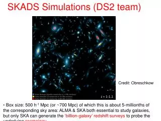
SKADS Benchmark Scenario . Andrew Faulkner . Design and Costing Process. Submitted to March ISSC Memo on SKADS website: www.skads-eu.org/PDF/SKADS_Benchmark_Scenario _D+C_v1.0.pdf Published as SKA Memo 93: www.skatelescope.org/PDF/memos/Memo_93.pdf.

E N D
SKADS Benchmark Scenario Andrew Faulkner
Design and Costing Process Submitted to March ISSC Memo on SKADS website: www.skads-eu.org/PDF/SKADS_Benchmark_Scenario_D+C_v1.0.pdf Published as SKA Memo 93: www.skatelescope.org/PDF/memos/Memo_93.pdf ‘Complete SKA concept’ Strong basis for moving forward
Top Frequency.... The cost vs frequency of a close packed aperture array varies as: Cost ≈freq2+ε+ infrastructure cost for ftop of 1.0 GHz < 50% cost for 1.4 GHz Science expt. requirementsdetermines ftop as ~1GHz
An overall SKA Scenario AA only realistic collector for <300MHz The SKADS Benchmark Scenario: • Small dishes lose efficiency at low freq. • AA gives v. fast survey speeds and can look for transients 100 - 300MHz Dipole aperture array <300 - 1000MHz Close packed aperture array 0.7 - 20+GHz 6-8m, dishes with single wideband feed • Low cost m-2 and they exist! • Large natural FoV • Good at high frequencies • Capable of mass production • WBFs could be >20:1 freq range • Single feeds can be cooled economically • Not suitable for arrays
Outline mid-freq AA spec Frequency range 300MHz – 1000MHz Organisation Close-packed (for now) Array size ~60m diameter (~300 tiles) Tsys <50K Bandwidth 700MHz Scan angle ±45° (target ±60°) Signal digitisation 4-bit
Filled FoV specification Low-AA: 200 deg2 Mid AA: 250 deg2 An AA can tailor this profile e.g. flat, λ2 etc. 6m Dish + WBF 3*(1.4/f)2 deg2 At 1.4GHz ... Ref: 5 deg2 B’mark: 3 deg2
Comms links Core (5Km dia), made up of close packed stations Central Processing in or near Core Station Desert Not to scale! Conceptual SKA Configuration
Station Processing Link to Correlator High freq. Dishes with analogue fibre link EoR AA antennas with analogue link (may be close packed) Notes: 1. Power dist. not shown 2. All analogue links go to ‘station processing’ Station
Bunker n x Optical fibres per 2nd stage processor High Freq. dishes 1st Stage Processors . Dish P1 . Station Processor 1 Dish P2 } .. . . Dish Px 20GHz Analog fibre links Station Processor 2 To Correlator Mid P1 Mid Freq. AA ….. Mid P2 . Mid Py Station Processor X 0.3-1.0GHz Analog links Internal Digital links Phase Standard & Distribution . Low Freq. AA Phase transfer over fibre (where used) . Low P1 Low P2 .. Control processors . . To Central Control system Low Pz 10Gb Digital fibre links 300MHz Analog links Station Processing RFI Barrier Only Analogue Digital Systems
Antenna Array… ~60m Tile Support Bunker • Contiguous array • Maintain from underneath • Cover with RF transparent sheet • Bunker in centre
Detailed design Design Blocks Antenna array Analogue signal transport Analogue beamforming Digital Beamforming 2nd Stage Processing Digital Data transport Dishes Mechanical Infrastructure
First costing result AA station Total: €3.1M Total: €1.9B Projected in 2011 €
PROS Design and engineering led Involved most engineering SKADS groups Focussed thinking on issues A complete SKA CONS Hard to vary the design: Mix of technologies Geometry Performance Technology based Light on ‘non-SKADS’ systems Central processing Dishes Connection to science Pros and Cons
Draft Specifications for theSquare Kilometre Array The output from a ‘Specification Tiger Team’: R. T. Schilizzi, P. Alexander, J. M. Cordes, P. E. Dewdney, R. D. Ekers, A. J. Faulkner, B. M. Gaensler, P. J. Hall, J. L. Jonas, K. I. Kellermann Covers science requirements and implementation trade-offs at fixed Cost covering three collector technologies. The principal input into SKA2007 Manchester: 27-28 September Available at: www.skatelescope.org
Sparse AA – element type 3 1000 Sparse AA – element type 2 Fully sampled AA Element type 1 Aeff 100 No new elements – maybe sparse above fAA Sky Brightness Temperature (K) Aeff / Tsys (m2 / K) 10000 10 Aeff/Tsys 5000 fsky fAA fmax 1 1000 100 500 1000 3000 Frequency (MHz)
SKA Spec: Key points • Describes options for SKA low and mid up to 10GHz • Has a Baseline design with Wide FoV technologies ‘expectations’ • All designs use 15m dishes • for risk mitigation: low frequency performance & computing cost • Restricted high frequency operation to 2020, high freqs to follow • Indicated performance for Key Science Projects AA for ≤500 MHz in All designs
TT proposals after SKA2007: Baseline Design Sparse AA: 70-200 MHz Sparse AA: 200-500 MHz 3100 x 15m dishes+WBSPF: <500 MHz–10GHz Focal Plane Array WFoV Sparse AA: 70-200 MHz Sparse AA: 200-500 MHz 1615 x 15m dishes+PAFs: 500 MHz–1.4 GHz +WBSPF: 1.5 GHz – 10 GHz Aperture Array WFoV Sparse AA: 70 – 200 MHz Sparse AA: 200 – 500 MHz Dense AA: 500 – 1000 MHz 3100 x 15m dishes+WBSPFs: 800 MHz – 10GHz There can be many variations!
D & C-2: Goals • Communicate SKADS D&C work Internationally • Bring science experiment reqts into the design process • Include new Design Blocks • Update existing Design Blocks with new information • Optimise System Configurations • Use information from other international groups
Some Challenges: From: Draft Specifications for the Square Kilometre Array
New Design Blocks Science drivers Central processing Array geometry Low System Noise
New Design Blocks Science drivers Central processing Array geometry Low System Noise
New Design Blocks Science drivers Central processing Array geometry Low System Noise Potentially a very big issue May be the highest system cost! Calculations by Tim Cornwell, see: SKA Memos: 49 and 64 The AAs could: be good – low N large D or bad – many beams, wide FoV
New Design Blocks Science drivers Central processing Array geometry Low System Noise Dense? Sparse?
New Design Blocks Science drivers Central processing Array geometry Low System Noise • Critical cost driver: 1 K worth ~€10M • or 2% more sensitivity • or 4% more survey speed • Sky noise important at these freqs • Minimise Trec then +Tsky = Tsys( f ) • All contributions must be investigated Key demonstration to the International community
Programme Timetable Initial D&C - 2 meeting 13 September 2007 Work on science reqts & system blocks Review Meeting 31 October 2007 Preparing written work + science & technical details Initial Drafts received 9 November Review Paper draft (telecon) 23 November Consolidating paper Final Draft 7 December Approval of Paper 11 December Publication of Paper 12 December SKA Specification Review Committee: Jan 2008