Download
1 / 18
180 likes | 286 Vues
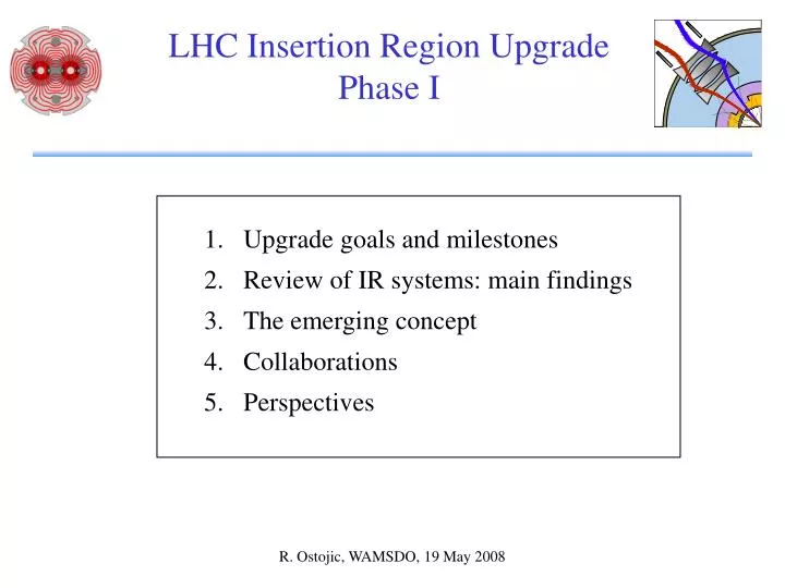
LHC Insertion Region Upgrade Phase I. Upgrade goals and milestones Review of IR systems: main findings The emerging concept Collaborations Perspectives. The LHC interaction regions. Final focus. Matching section. Separation dipoles. Dispersion suppressor. LHC high-luminosity IRs:

E N D
LHC Insertion Region UpgradePhase I Upgrade goals and milestones Review of IR systems: main findings The emerging concept Collaborations Perspectives R. Ostojic, WAMSDO, 19 May 2008
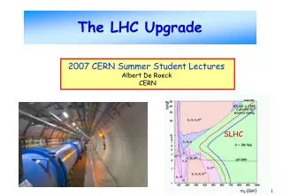
The LHC interaction regions Final focus Matching section Separation dipoles Dispersion suppressor • LHC high-luminosity IRs: • Triplet gradient 205 T/m • Triplet aperture • Coil 70 mm • Beam screen 60 mm b* = 0.55 m L = 1034 • Power in triplet ~ 200 W @ 1.9 K
LHC IR Upgrade - Phase I Goal of the upgrade: Enable focusing of the beams to b*=0.25 m in IP1 and IP5, and reliable operation of the LHC at 2 1034 cm-2s-1 on the horizon of the physics run in 2013. Scope of the Project: • Upgrade of ATLAS and CMS interaction regions. The interfaces between the LHC and the experiments remain unchanged. • Replace the present triplets with wide aperture quadrupoles based on the LHC dipole cables (Nb-Ti) cooled at 1.9 K. • Upgrade the D1 separation dipole, TAS and other beam-line equipment so as to be compatible with the inner triplet aperture. • Modify matching sections (D2-Q4, Q5, Q6) to improve optics flexibility. Introduction of other equipment to the extent of available resources. • The cryogenic cooling capacity and other infrastructure in IR1 and IR5 remain unchanged and will be used to full capacity.
Project milestones Project Approval Dec 2007 Conceptual Design Report June 2008 Model quadrupole end 2009 Technical Design Report mid 2009 Pre-series quadrupole end 2010 String test 2012 Installation shutdown 2013
Review of IR systems: main findings (1) • IR optics and aperture requirements • Most promising solutions: “symmetric” and “low-beta-max” triplets. • D1 dipole must match the aperture of the triplet. • The present matching sections (D2-Q4, Q5) limit the reach of the triplet. Modifications of magnet positions and aperture (beam screens) may be needed. • Collimation and optics • The main concern is the collimation efficiency in IR7. • Squeezing b* drives chromatic aberrations, which may corrupt the collimation hierarchy. A new solution for arc and insertion optics is necessary to minimize these effects. • Larger triplet aperture opens the possibility of opening the jaws and reducing the collimator impedance. However, the efficiency of collimation decreases.
Review of IR systems: main findings (2) 3. Cold vacuum • Vacuum stability remains an issue, irrespective of larger aperture beam screens (continue to be) required. • Mechanical stability during quench (~ r5), beam screen thickness 2mm. • Vacuum conditions allow beam screen cooling at 40-60 K level. • Main concerns: gas load (beam screen transparency) and average gas density (background). 4. Powering and protection • Quench protection must be considered from the beginning as an integral part of the string design. Due to considerably higher stored energy, the magnet protection should be decoupled and energy extraction included. • All electronics equipment (including DFBX) must be located outside the tunnel. Severe space constraints around IP1 and IP5. • The favoured powering scheme consists of one main PC (13 kA), trim PC for each magnet, and circuit protection with warm thyristors.
Review of IR systems: main findings (3) 5. Energy deposition • The baseline parameters of the triplet, including the cold bore and beam screen (~6 mm total), result in a longitudinal distribution of losses where the critical area is the Q1-Q2 region. • The protection of the Q2 and Q3 magnets is ensured with the baseline cold bore and beam screen. Additional absorber in Q1 can effectively reduce the power density peaks in the Q1-Q2 region. • Recent studies of polyimide insulation schemes show a large potential for increasing the power extracted from the coil (a factor of ~5 higher than the nominal LHC insulation). • The total deposited power is ~380 W. Average power is ~10 W/m. BS/absorber catches 10-30% of the total (~3 W/m). 6. Cryogenic limitations • New “ultimate” beam conditions compatible withavailable plant capacity to be defined after LHC commissioning. • As the RF in IP4 is cooled by the LHC cryoplant, the triplet in 5L may have less cooling capacity available than the others. • Replacement of triplets in IR1/5 requiresat present warm-up of 4 sectors.
Review of IR systems: main findings (4) 7. Options for D1 magnet • Several possibilities for D1 considered: NC, SC and superferric magnets. • A large aperture 4 T SC dipole is the most cost effective and opens the possibility of using the space in between D1-D2 for other equipment (e.g. crab cavities). Drawbacks: sharing of cryogenic power (1.9 K or 4.5K) and need for a local power converter. • Interfaces with the experiments and the tunnel • Replacement of the TAS vacuum chamber with a larger aperture one requires removal of the TAS and its shielding from the experimental caverns. Very tight interfaces of the TAS with the shielding, survey equipment and beam instrumentation; no possibility of reducing L* (23m). • Access and transport from the surface to IR1/5 require that the diameter and length of the vacuum vessels of the new triplets are similar to the LHC main dipole (OD 914 mm, l < 14 m). • Re-use of the main components and assembly procedures for cryostating limits the cold mass to OD 570 mm.
The emerging concept (1) Optics • Correction of chromatic aberrations in IR3, IR7 and in the inner triplets in IR1 and IR5 requires re-phasing of all arcs and insertions for b* < 0.5 m. The strength of the arc sextupoles limits b* to 0.25 m. • To improve the tuning flexibility of IR1 and IR5, determined by the bmax (length of the triplet), Q4 (D2) and Q5 in IR1/5 mayneed to be movedby ~15 m towards the arc. • Parasitic dispersion in the triplets due to large crossing angle has to be controlled. Beam crossing schemes in IP1 and IP5 need to be conform. Triplet: • Composed of four cryo-quadrupoles of similar length (~ 9 m). • Cold bore+beam-screen engineered as protection elements; beam screen cooled at 40-60 K. • Interconnections identical in IR1 and IR5. • Dipole and multipole correctors grouped in a separate cryo-unit located in between D1 and Q3.
The emerging concept (2) Powering • Each magnet protected separately. Energy extraction included in the main circuit; trims for adjustment of each magnet. • All delicate equipment moved into shielded areas. DFBX connected to the triplet with a SC link (HTS or LTS). Low-b quadrupoles • Magnet aperture defined using as ultimate parameters b*=0.25 m and n1=7 (definitions and tolerances as for nominal LHC). This leads to a beam-stay-clear of ~95 mm, coil ID of ~ 110 mm and field gradient of ~130 T/m. • Final choice of the magnet parameters to take into account the optimal useof existing cable and evaluation of margins.
The emerging triplet layout QRL D1 CP Q3 Q2B Q2A Q1 ~5 m ~1.6 ~9 m ~1.6 ~8 m ~1.6 ~8 m ~1.6 ~9 m DFBX • DFBX, power converters, energy extraction and protection electronics located in shielded areas outside the LHC tunnel. • Quadrupoles powered in series with individual trims. • All correctors grouped in a separate cryo-unit (CP). • D1 is a SC dipole.
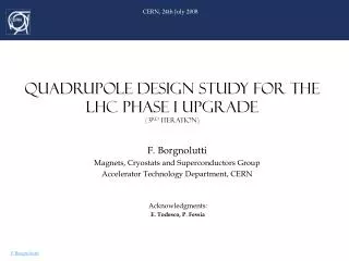
Issues for Nb-Ti quad design Fixed parameters SC cable: LHC dipole cables Collar material:Nippon Steel YUS 130 (thickness 3 mm) Yoke material: Cockerill steel (thickness 5.8 mm) Cold mass outer diameter: 570 mm (iron yoke 550mm and shell thickness 10 mm). Issues • Optimal use of available cable (width and length). • New cable insulation scheme for improved heat transfer. • Design of the mechanical structure to support high forces. • Collar and yoke transparency to improve coupling to the cold source. • Integration of the heat exchanger.
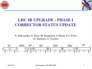
A corrector cryo-unit (CP) MQSX MCSTX MCBH MCBV ~2 m ~2 m ~0.5 m ~0.5 m
Collaborations CERN EU-FP 7 SLHC-PP • Quadrupole production • Cryostating • Powering and protection • Design and construction of the model quad • Design of the correctors • Design of the cryostats LHC IR upgrade phase I Special French contribution US-LAUC • Cryostating components • Quadrupole components • Production of the correctors • D1 separation dipole • Cold powering
Perspectives • The discussions on the “LHC IR upgrade – Phase I” have allowed to identify the constraints and the main performance issues. The layout concept and magnet parameters are gradually emerging. The conceptual design report on track for June 2008. • A certain number of technical choices still need to be made (e.g. cooling of the correctors and D1 separation dipoles). The tunnel environment and the cost implications will be the major drivers in the decision process. • The collaborations with European and US teams off to a good start. Discussions on some organisational aspects and technical interfaces to be completed as part of the preparation of the technical design report. QA procedures developed for LHC construction will be systematically used for Project follow-up.