Download
1 / 87
990 likes | 1.39k Vues
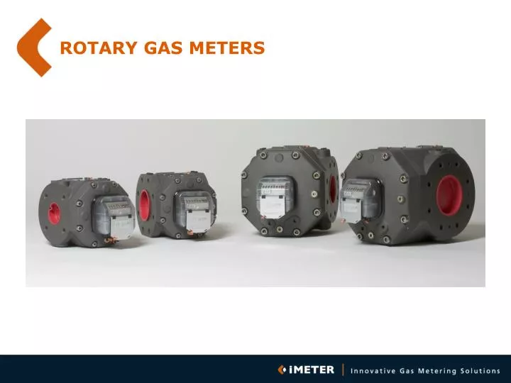
ROTARY GAS METERS. TYPICAL APPLICATIONS. PRESSURE. 100bar. Turbine. 16bar. TWIN Rotary / Turbine. 4bar. Rotary. 30 mbar. D. 40 m3/h. 400 m3/h. 1000 m3/h. 4000 m3/h. CAPACITY. RANGEABILITY. RANGEABILITY. TIME. LOAD PROFILE. CAPACITY. INDUSTRIAL. COOCKING. HEATING. BOILER.

E N D
TYPICAL APPLICATIONS PRESSURE 100bar Turbine 16bar TWIN Rotary / Turbine 4bar Rotary 30 mbar D 40 m3/h 400 m3/h 1000 m3/h 4000 m3/h CAPACITY
RANGEABILITY RANGEABILITY TIME LOAD PROFILE CAPACITY INDUSTRIAL COOCKING HEATING BOILER
RANGEABILITY OPTIMIZED ROTARY METER CONVENTIONAL ROTARY METER TURBINE METER TIME LOAD PROFILE CAPACITY INDUSTRIAL COOCKING HEATING BOILING
OPERATING PRINCIPLE • DISPLACEMENT PRINCIPLE • DISPLACED VOLUME: TWO ROTATIONS
OPERATING PRINCIPLE SEAL
LEAKAGE LEAKAGE LEAKAGE ERROR OF INDICATION ERROR 1% NO LEAKAGE 0% CAPACITY -1% SMALL LAEKAGE LARGE LEAKAGE
LEAKAGE IS RELATED TO IMPELLER DIMENSIONS AND TOLERANCES L S W H 3 (2L + 2H) x S LEAKAGE = W
TURN DOWN RATIOS WITH NATURAL GAS LEAKAGE = FUNCTION OF VISCOSITY VISCOSITY AIR = VISCOSITY NATURAL GAS
SEAL GAP: 0,15 mm (1 : 50) 0,12 mm (1 : 100) 0,10 mm (1 : 160)
PULSATION 14% Actual flow Time
PULSATION • - Reducer • Bend • Valve • Longitudual Wave: • Significant Error • High Noise Level • Bearing Damages
PULSATION Error of Indication (%) • Error depends on: • Installation • Pressure • Meter Type/Brand 1 capacity -1
TRANSPORTATION USE PROTECTION COVERS
INSTALLATION STRESS PARALEL AND ALIGNED • CONVENTIONAL METERS ARE • SENSITIVE TO INSTALLATION • STRESSES • INSTALLATION STRESS CAN • LOCK UP THE METER • NO SUCURITY OF SUPPLY
HARD COATING WETTED PARTS WITHOUT HARD COATING THE METER PERFORMANCE WILL DEGRADE AND WILL FINALLY LOCK UP
RIGID DESIGN • Non-rigid designs are sensitive to • fast starting up (common practice) • Meters will lock up • No security of supply
STARTING UP 50 m PIPE LINE 4 bar FILLING THE PIPE LINE WILL OVERLOAD THE METER SHORTLY 500% ! ¼ x D
INSTALLATION SEEVE PREFERED
INSTALLATION SEEVE SEEVE
INSTALLATION DIRTY GAS: CONE SIEVE (CAN HANDLE 5 TIME MORE DIRT)
INSTALLATION NO LUBRICATED PLUG VALVES UP STREAM THE METER
INSTALLATION OR USE CONE FILTERS (ROTARY AND TURBINE)
INSTALLATION CLEAN THE INLET
INSTALLATION No grease on Gaskets
INSTALLATION 3 2 1 4 Cross wise
INSTALLATION Oil level
INSTALLATION Oil level
IMRM ROTARY METER G25 (11/2”) – G250 (4”)
IMRM FEATURES Conform Latest and Future Directives (EEC, EN and OIML) Square Impeller Technology Turn Down Ratio > 1:160 (EN12480) Rigid Construction Not Sensitive to Installation Stresses Thermical Balanced 150% Overload permitted Front Reading/Servicing On-Site or Local Repair
REGISTRATION FUNCTIONALITY SENSOR INDEX COMMUNICATION SEPERATION FUNCTIONS(CONFORM OIML)
LARGE TURN DOWN RATIO IMRM Rotary Meter Conventional Rotary Meter Turbine Meter Time LOAD DURATION CURVE Load HEATING COOLING HEATING COOLING COOKING BOILER
LEAKAGE LEAKAGE LEAKAGE LEAKAGE IS UNREGISTERED LOSS error 2% No leakage 0% capacity -2% Large leakage Small leakage
SQUARE IMPELLERS L S W H 3 (2L + 2H) x S LEAKAGE = W
iMRM Quadratic Impellers CONVENTIONAL SQUARE
SQUARE CONVENTIONAL
IMRM RANGEABILITY >1:160 ERROR (%) 1 CAPACITY >1:100 -1
iMRM Rigid Construction
STAINLESS STEEL BEARING SUPPORT Temperature Influence < 0.007% per degree C. >50% Overload Permitted Exchangeable Bearing Sizes (High Pressure Application, Specials) STAINLESS STEEL
iMRM Stainless Steel Bearing Support
RIGID METER BODY RIGID METER BODY means Less sensitive to Installation Stress
iMRM RIGID METER BODY
INSTALLATION - Suitable for Installation to the Wall - All Plugs in Front
iMRM INSTALLATION
IMRM: ON-SITE REPAIR BALL BEARINGS
iMRM REPAIRABLE BEARINGS BALL BEARINGS