Download
1 / 19
190 likes | 396 Vues
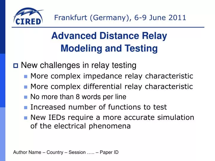
Advanced Distance Relay Modeling and Testing. New challenges in relay testing More complex impedance relay characteristic More complex differential relay characteristic No more than 8 words per line Increased number of functions to test

E N D
Advanced Distance Relay Modeling and Testing • New challenges in relay testing • More complex impedance relay characteristic • More complex differential relay characteristic • No more than 8 words per line • Increased number of functions to test • New IEDs require a more accurate simulation of the electrical phenomena Author Name – Country – Session ….. – Paper ID
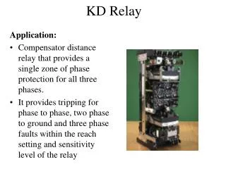
Distance relay modeling • Unlike old relays, new impedance characteristics are more complex • The test engineer must deeply know all relay features • The new Toshiba GRZ100 has a very challenging impedance characteristic
The relay characteristic is not just a series of lines and arcs • It is the intersection of different comparators
In RIO format, that shape is defined as • LINE 7.212389, 0.7926472, 75 • ARC 2.588202, 9.659244, 10, 32.45674, 56.51973 • LINE 8.1047, 18, 180 • ARC 2.588191, 9.659257, 10, 123.4804, 165 • LINE -7.071067, 12.24745, -60 • LINE 0, 0, -10 • ARC 2.58819, 9.659258, 10, 265, 297.5433 It is evident it is not something that can be easily done by hand.
The importance of a library... • For this reason, several relay test set manufacturers offer a library • The purpose is to automatically define that sequence of arcs and lines which depends on the extension of the circular characteristic And until now, nothing new
New ways to define the characteristics • The characteristic is always defined as a result of the intersection of different comparator. • The result is a series of line and arcs • And it represents just one single characteristic... But what if we use two characteristics to represent one ?
Use the same (almost) method of the relays... • As we already said... • So that we can say, if that is zone 1 • Zone 1 = Z1MHO ∩ Z1QUAD This MHO And this poligonal
So that if the draw two simple char • Zone 11: MHO • Zone 12: Poligonal • The nominal char can simply been calculated as Znom = Min (Zquad, Zmho) • The testing software must simply evaluate 2 impedance values and take the minimum
In the same way... A Characteristic like the SEL321 will be union of 2 shapes + = • In this case: Zone 1 = Z1MHO U Z1QUAD • and ... Znom = Max (Zquad, Zmho)
This is very useful in many cases • ... Like in the general fault criteria and the
Conclusion for part 1 • This approach will enhance the productiveness of the technicians • But it will change the method of exporting the impedance relay nominal characteristic • formats like the actual RIO would be insufficient In fact, although it makes possible to define whatever number of zones, it is not giving information whether a single zone is the combination of more shapes.
Getting close to a real fault simulation • Modern protective relays implement special algorithms to enhance the relay operating time in zone 1. • A trip time below 1 cycle is required for EEHA lines. • To work properly, the currents seen by the relay must have a smooth change from pre-fault to fault
The DC offset • It is not easy to have this simulation at any time • It requires the software or hardware to evaluate this equation at every transition • Where • I1 = RMS value of the fault current • I0 = instantaneous value of the current just before the fault • = Time constant • t = Time in seconds, fault occurs at t=0
This can be done with Comtrade files ? • It is a strategy to perform a single shot test, but... • A total of • 6 channels • With fault duration of 1.2 s • sampled at 1 kHz • 2 bytes per sample • Requires a file of 720 kB to be uploaded • With a 10 Mbps or 100 Mbps this can be uploaded very quickly, therefore it might not be a problem
But what about developing faults ? • A developing fault is a sequence of states where every state depends on what happened in the previous state • Due to this, a Comtrade has the limitation that the exact time of transition between states is not certain • The exact time of transition determines the DC offset of the currents in the following state
The DC offset calculated on the fly • Due to this, the DC offset must be evaluated by the hardware itself • The firmware of the equipment must be able to elaborate, at high speed, this formula • Since the sampling rate of the genaration must be kept relatively high, 10 to 20 kHz, for all current involved in the test
Failing to do that, a simulation like the following would become impossible
Conclusion for part 2 • Nowaday, testing a relay is not simply a characteristic check • Smarter relays require smarter test equipments • Smarter test equipment require high speed dedicated processors • We have answers to all testing problems may arise in the field.
Thanks very muchfor your attention Mauro Borrielli Doble engineering company Client support engineer Email: mauro.borrielli@doble.no Web: www.doble.com