Download
1 / 77
780 likes | 880 Vues
GSM Protocol Stack Shrish Mammattva Bajpai. What is Protocol Stack ?.

E N D
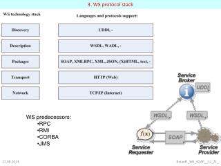
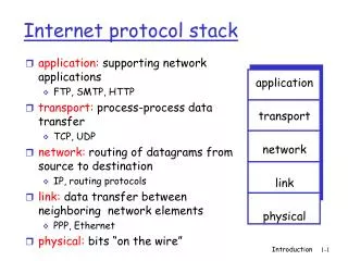
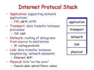
What is Protocol Stack ? A protocol stack (sometimes communications stack) is a particular software implementation of a computer networkingprotocol suite. The terms are often used interchangeably. Strictly speaking, the suite is the definition of the protocols, and the stack is the software implementation of them. In Windows the TCP/IP stack is implemented by the Winsock DLL.
What is Protocol Stack ? The term stack also refers to the actual software that processes the protocols. So, for example, programmers sometimes talk about loading a stack, which means to load the software required to use a specific set of protocols.
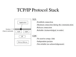
MS End Protocol Stack • Physical Layer • Data Link Layer • Layer 3 Radio Recourse Management Mobility Management Connection Management
BTS End Protocol Stack • Physical Layer • Data Link Layer • Layer 3 Radio Recourse Base Transreceiving Station Management
BSC End Protocol Stack • Physical Layer • Data Link Layer • Layer 3 Radio Recourse Base Tranreceiving Station Management Signaling Connection Control Part Direct Transfer Application Part Base Station Subsystem Management Application Part
MSC End Protocol Stack Message Transfer Part Signaling Connection Control Part Direct Transfer Application Part Base Station Subsystem Management Application Part Connection Management Mobility Management Mobile Application Part Transaction Capabilities Application Part.
Um Interface • Physical Layer Implement Logic channels,coding and frames. Access Capabilities. Error Detection. Encryption.
Um Interface Physical Layer Mode • Mode of operations Idle Mode. Dedicated Mode.
Um Interface Physical Layer Frame • 21 Blocks. • Power level. • Timing advance. Use by ACCH, CCCH, BCCH & DCCH.
Um Interface Data Link Layer Operation Mode 1 • Unacknowledged Operation Data Transmitted in UI frame. No Ack No Flow control Mechanism. No L2 error correction technique. Use for all channels except RACH. .
Um Interface Data Link Layer Operation Mode 2 • Acknowledged Operation Mode Data Transmitted in I frame. + Ve Ack Flow control Mechanism. Error correction technique. Use for DCCH Channel
Um Interface Data Link Layer Connection End Point Identifiers of L2 connections are labeled with Data Ling Layer Identifiers 1.Service Access End Point Identifiers 2.Connection End Point Identifiers SAPI =0 for Signaling. SAPI = 3 for SMS.
Um Interface Data Link LayerProcedure 1 • Distribution Procedure SAP is associated with only one signaling channel Distribution of L2 frame receive by one channel to the respective data link procedure. Not used for RACH
Um Interface Data Link LayerProcedure 2 • Random Access Procedure Only for RACH Unidirectional Procedure Deals with random control procedure Retransmission of Random Access Brust
Um Interface Data Link LayerFrame Formats 1 Points No flag at start and at last. Octets are depend upon type of channel. The end of information field is given by length indicator. Frame format contains address field and variable length. Connection of SAPI = 0 is initiated by MS. Address Field is one for control channels
Um Interface Data Link LayerFrame Formats • Type A. Used in dedicated channels Bi-directional Use. No Information Contain. Ack Mode Operation.
Um Interface Data Link LayerFrame Formats • Type B. Used in dedicated channels Bi-directional Use. Information Contain. Ack Mode Operation.
Um Interface Data Link LayerFrame Formats • Type Bbis Used in common control channels Uni-directional Use. Information Contain. Un Ack Mode Operation. SAPI =0 is used.
Um Interface Data Link LayerFrame Formats • Type Abis Used in common control channels Uni-directional Use. No Information Contain. Un Ack Mode Operation. SAPI =0 is used.
Um Interface Layer 3 • Layer 3 RR Management. CM Management. MM Management.
Um Interface Layer 3 Frame Format 1 • Common for RR, MM and CM.
Um Interface Layer 3 Frame Format 2 • Transaction ID- Enable to perform several parallel signaling transaction. • Protocol Discriminator – Operation type. • Message Type – Different type of process. • Information ID – Information elements. • Length Indicator – Length of the Information ID.
Um Interface Layer 3 Radio Recourse Management. Processes • Connection Set Up And Release. • Handoff. • Channel Change • Ciphering.
Um Interface Layer 3 Radio Recourse Management. Connection Set Up And Release Processes
Um Interface Layer 3 Radio Recourse Management. Connection Set Up And Release Processes
Um Interface Layer 3 Radio Recourse Management. Connection Set Up And Release Processes
Um Interface Layer 3 Radio Recourse Management. Connection Set Up And Release Processes • RR Connection between MS & Nwk.. • LAPDm Connection between MS & Nwk.. • Initiated by MS or Nwk. . • RR connection Establish then higher link comes in picture. • SAPI =0 is used.
Um Interface Layer 3 Radio Recourse Management. Channel Change Processes
Um Interface Layer 3 Radio Recourse Management. Channel Change Processes • Requested By CM, MM or by RR. • Initiated By Nwk.. • MS get assignment command to shut down the connection.
Um Interface Layer 3 Radio Recourse Management. Handoff Process
Um Interface Layer 3 Radio Recourse Management. Handoff Process
Um Interface Layer 3 Radio Recourse Management. Handoff Process • Cell Information BCCH • Handoff Command ACCH • Handoff Access DCCH
Um Interface Layer 3 Radio Recourse Management. Activation of Ciphering Process
Um Interface Layer 3 Radio Recourse Management. Activation of Ciphering Process • Done By BSS. • MS get the message and done the task.
Um Interface Layer 3 Mobility Management Process • Common Mobility Management Process. TMSI Assignment. Identification Process. Authentication Process. IMSI Detach. • Specific Mobility Management Process IMSI Attach Location Updation. MM Connection Management Process