Download
1 / 14
150 likes | 479 Vues
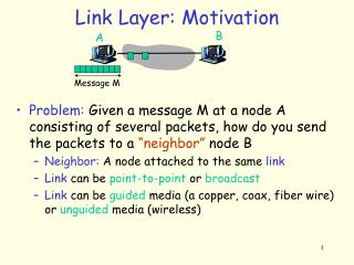
5.1 Introduction and services 5.2 Error detection and correction 5.3 Multiple access protocols 5.4 Link-layer Addressing 5.5 Ethernet. 5.6 Link-layer switches 5.7 PPP 5.8 Link Virtualization: ATM, MPLS. Link Layer. twisted pair. hub. Hubs. … physical-layer (“dumb”) repeaters:

E N D
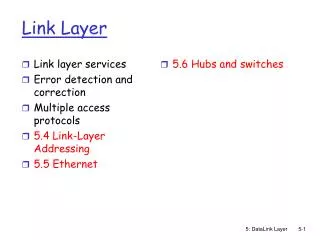
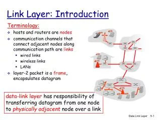
5.1 Introduction and services 5.2 Error detection and correction 5.3 Multiple access protocols 5.4 Link-layer Addressing 5.5 Ethernet 5.6 Link-layer switches 5.7 PPP 5.8 Link Virtualization: ATM, MPLS Link Layer 5: DataLink Layer
twisted pair hub Hubs … physical-layer (“dumb”) repeaters: • bits coming in one link go out all other links at same rate • all nodes connected to hub can collide with one another • no frame buffering • no CSMA/CD at hub: host NICs detect collisions 5: DataLink Layer
Switch • link-layer device: smarter than hubs, take active role • store, forward Ethernet frames • examine incoming frame’s MAC address, selectively forward frame to one-or-more outgoing links when frame is to be forwarded on segment, uses CSMA/CD to access segment • transparent • hosts are unaware of presence of switches • plug-and-play, self-learning • switches do not need to be configured 5: DataLink Layer
Switch: allows multiple simultaneous transmissions A • hosts have dedicated, direct connection to switch • switches buffer packets • Ethernet protocol used on each incoming link, but no collisions; full duplex • each link is its own collision domain • switching:A-to-A’ and B-to-B’ simultaneously, without collisions • not possible with dumb hub C’ B 1 2 3 6 4 5 C B’ A’ switch with six interfaces (1,2,3,4,5,6) 5: DataLink Layer
Switch Table A • Q: how does switch know that A’ reachable via interface 4, B’ reachable via interface 5? • A: each switch has a switch table, each entry: • (MAC address of host, interface to reach host, time stamp) • looks like a routing table! • Q: how are entries created, maintained in switch table? • something like a routing protocol? C’ B 1 2 3 6 4 5 C B’ A’ switch with six interfaces (1,2,3,4,5,6) 5: DataLink Layer
Source: A Dest: A’ MAC addr interface TTL 60 1 A A A’ Switch: self-learning A • switchlearns which hosts can be reached through which interfaces • when frame received, switch “learns” location of sender: incoming LAN segment • records sender/location pair in switch table C’ B 1 2 3 6 4 5 C B’ A’ Switch table (initially empty) 5: DataLink Layer
Switch: frame filtering/forwarding When frame received: 1. record link associated with sending host 2. index switch table using MAC dest address 3. if entry found for destinationthen { if dest on segment from which frame arrivedthen drop the frame else forward the frame on interface indicated } else flood forward on all but the interface on which the frame arrived 5: DataLink Layer
Source: A Dest: A’ A’ A MAC addr interface TTL 60 60 1 4 A A’ A A’ A A’ A A’ A A’ A A’ A A’ Self-learning, forwarding: example A • frame destination unknown: C’ B 1 2 3 flood 6 4 5 • destination A location known: C selective send B’ A’ Switch table (initially empty) 5: DataLink Layer
S4 S3 S2 F I D H G E Interconnecting switches • switches can be connected together S1 A C B • Q: sending from A to G - how does S1 know to forward frame destined to F via S4 and S3? • A: self learning! (works exactly the same as in single-switch case!) 5: DataLink Layer
Self-learning multi-switch example Suppose C sends frame to I, I responds to C S4 1 S1 2 S3 S2 A F I D C B H G E • Q: show switch tables and packet forwarding in S1, S2, S3, S4 5: DataLink Layer
Institutional network mail server to external network web server router IP subnet 5: DataLink Layer
Switches vs. Routers • both store-and-forward devices • routers: network layer devices (examine network layer headers) • switches are link layer devices • routers maintain routing tables, implement routing algorithms • switches maintain switch tables, implement filtering, learning algorithms 5: DataLink Layer
Hierarchical Switch Problems Hierarchical scheme shown in 5.26 looks like a great idea, but there are some issues: • Lack of traffic isolation: ARP and DHCP • Inefficient use of switches when assigning users to a group switch (think collision domain) S4 1 S1 2 S3 S2 A F I D C B H G E
Virtual Local Area Networks (VLANs) • Switch breaks the physical LAN into several VLANs, possibly on the same switch. • VLAN trunking across multipl switches • What does VLAN look like?