Download
1 / 19
200 likes | 570 Vues
Deformation. Let me tell you the secret that has led me to my goal. My strength lies in my tenacity. Louis Pateur. Image: High speed photographs of a club striking a golf ball. Note the large deformations in the golf ball. Normal Stress. Figure 5.6 Element subjected to normal stress.

E N D
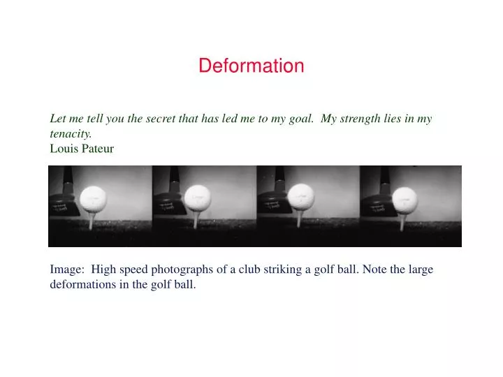
Deformation Let me tell you the secret that has led me to my goal. My strength lies in my tenacity. Louis Pateur Image: High speed photographs of a club striking a golf ball. Note the large deformations in the golf ball.
Normal Stress Figure 5.6 Element subjected to normal stress text reference: Figure 5.6, page 195
Shear Stress Figure 5.7 Element subjected to shear stress. text reference: Figure 5.7, page 197
Twisting due to Applied Torque Figure 4.11 Twisting of member due to applied torque. Hipotesis de Coulomb: secciones transversales circulares, permanecen planas. Principio de Saint Venant: secciones transversales no circulares. text reference: Figure 4.11, page 152
Example 5.1 Figure 5.1 Cantilevered beam with concentrated force applied at free end. Used in Example 5.1. text reference: Figure 5.1, page 184
Examen septiembre 2006 1/ Un resorte de una puerta tiene sección rectangular 50x6 (mm) y longitud 800 mm. Uno de sus extremos se haya empotrado y en el otro se producen deflexiones entre 75 y 150 mm cíclicamente. Determinar el coeficiente de seguridad en la sección más peligrosa en: a) caso citado b) si a L/2 se le practica un taladro de O 12,5mm. Condiciones de carga de (a) Material estirado en frio, E=210Gpa, Su=1034MPa y ν= 0,3 Fiabilidad 90% aT=20ºC…………3 puntos text reference: Figure 5.1, page 184
Cantilever with Moment and Concentrated Force Figure 5.5 Bar fixed at one end and free at other with moment applied to free end and concentrated force at any distance from free end. (a) Complete assembly; (b) free-body diagram showing effect of concentrated force; (c) free-body diagram showing effect of moment. text reference: Figure 5.5, page 194
Example 5.8 Figure 5.8 Cantilevered bar with concentrated force acting at distance b from free end. (a) Coordinate system and important points shown; (b) fictitious force shown along with concentrated force. text reference: Figure 5.8, page 203
Free Body Diagram of Simply Supported Beam Figure 5.2 Free-body diagram of force anywhere between simply supported ends. (a) Complete bar; (b) portion of bar. text reference: Figure 5.2, page 187
Cantilevered Bar with Partial Distributed Load Figure 5.3 Cantilevered bar with unit step distribution over part of bar. (a) Loads and deflection acting on cantilevered bar; (b) free-body diagram of forces and moments acting on entire bar; (c) free-body diagram of forces and moments acting on portion of bar. text reference: Figure 5.3, page 189
Cantilever with Simply Supported End Figure 5.4 Cantilevered bar with other end simply supported and with concentrated force acting anywhere along bar. (a) Sketch of assembly; (b) free-body diagram of entire bar; (c) free-body diagram of part of bar. text reference: Figure 5.4, page 191
Deflection of Beams Table 5.1 Deflection for three different situations when one end is fixed and one end is free and two different situations of simply supported beams. text reference: Table 5.1, page 193
Deflection of Beams (cont.) Table 5.1 Deflection for three different situations when one end is fixed and one end is free and two different situations of simply supported beams. text reference: Table 5.1, page 193
Método del momento de área La distancia vertical entre un punto cualquiera A en la curva de flexión y la tangente a la curva en otro punto B es igual al momento estático con respecto a A del área del diagrama del momento flexionante entre A y B, dividido entre la rigidez.
Strain EnergyAplicación: Método de Castigliano Table 5.2 Strain energy for four types of loading. text reference: Table 5.2, page 200
Example 5.9 Figure 5.9 Cable system arrangement. (a) Entire assembly; (b) free-body diagram of forces acting at point A. text reference: Figure 5.9, page 204
Example 5.10 Figure 5.10 Cantilevered bar with 90° bend acted upon by horizontal force at free end. text reference: Figure 5.10, page 205
Design of FOPS Figure 5.11 Figures used in case study. (a) Forklift truck; (b) FOPS details (not to scale); (c) idealized FOPS for analysis. text reference: Figure 5.11, page 207
FOPS Cross Brace Analysis Figure 5.12 (a) Free-body; (b) shear; and (c) bending moment diagrams for FOPS cross brace. text reference: Figure 5.12, page 208