Download
1 / 34
350 likes | 970 Vues
SNAP OTA Baseline TMA62. M.Lampton Jan 2002 UC Berkeley Space Sciences Lab. SNAP Mission Plan. Preselect ~20 study fields, both NEP and SEP Discoveries & photometric light curves from repeated deep images huge multiplex advantage with “batch” observations, 1E9 pixels

E N D
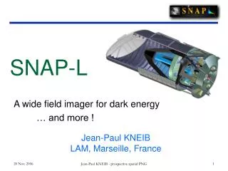
SNAP OTA Baseline TMA62 M.Lampton Jan 2002 UC Berkeley Space Sciences Lab
SNAP Mission Plan • Preselect ~20 study fields, both NEP and SEP • Discoveries & photometric light curves from repeated deep images • huge multiplex advantage with “batch” observations, 1E9 pixels • Spectroscopy near maximum light from followup pointings Deep Surveys: N S N S Followup spectroscopy: ~4 day period
SNAP • Simple Observatory consists of : • 1) 3 mirror telescope w/ separable kinematic mount • 2) Baffled Sun Shade w/ body mounted solar panel and instrument radiator on opposing side • 3) Instrument Suite • 4) Spacecraft bus supporting telemetry (multiple antennae), propulsion, instrument electronics, etc • No moving parts (ex. filter wheels, shutters), rigid simple structure.
Annular Field Three Mirror Anastigmat • Aperture: 2 meters • Field of view: > 1 square degree • 1.37 square degrees in TMA62 • Diffraction limited longward of one micron • 2 microns RMS, 15microns FWZ geometric • Flat field • Folded to obtain short overall length • 3.3 meters in TMA62
Wide-Field Telescope: History • Wide-field high-resolution telescopes are NOT new • Schmidt cameras (1930 to present) • Field-widened cassegrains, Gascoigne (1977-); SDSS • Paul three-mirror telescopes (1935) and Baker-Paul • Cook three-mirror anastigmats (1979) • Williams TMA variants (1979) • Korsch family of TMAs (1972...) • Angel-Woolf-Epps three-mirror design (1982) • McGraw three-mirror system (1982) • Willstrop “Mersenne Schmidt” family (1984) • Dark Matter Telescope (1996+) • New Planetary Telescope (1998) • IKONOS Earth resources satellite (1999) • FAME astrometric TMA • Multispectral Thematic Imager (1999)
Three-mirror anastigmat (TMA) • Identified as best choice for SNAP • Can deliver the required FOV • Can deliver the required resolution • Inherently achromatic, no correctors needed • Inherently flat field • Inherently elastic: 9 d.o.f. to meet 4 Seidel conditions plus focus & focal length • Can meet packaging requirements
Telescope: Downselection • 1999-2001: Suitability Assessments • sought 1 sq deg with diffraction limited imaging (< 0.1 arcsec) • low obscuration is highly desirable • off-axis designs attractive but unpackagable; rejected • four, five, and six-mirror variants explored; rejected • eccentric pupil designs explored; rejected • annular field TMA concept rediscovered & developed • TMA43 (f/10): satisfactory performance but lacked margins for adjustment; lateral axis between tertiary & detector • TMA55 (f/10): improved performance, margins positive, common axes for pri, sec, tertiary. • TMA56 (f/10) like TMA55 but stretched • TMA59 (f/15): same but with longer focal length • TMA62 (f/10.5) lateral axis between tertiary & detector
Baseline Telescope • Baseline Optical System: Annular Field TMA62 • prolate ellipsoid concave primary mirror • hyperbolic convex secondary mirror • flat annular folding mirror • prolate ellipsoid concave tertiary mirror • flat focal plane • provides side-mounted detector location for best detector cooling • EFL = 21.66m matches 10.5 micron SiCCD pixel to 0.1 arcsec angular scale • plate scale is 105 microns per arcsecond • delivers annular field 1.37 sqdeg • average geometrical blur 2.5umRMS = 6umFWHM; 16um worst case FWZ • compare: SiCCD pixel = 10.5 um; HgCdTE pixel 18.5um • angular geometrical blur 0.023arcsecRMS =0.06arcsecFWHM • compare: Airy disk, 1um wavelength: FWHM=0.12arcsec=13um
Annular Field Dimensions • Outer radius: 0.745 degrees • corresponds to 283.56 mm at detector • Inner Radius: 0.344 degrees • corresponds to 129.1 mm at detector • Sky coverage 1.37 square degree • corresponds to 1957 cm2 detector area • Field Blockages-- none • Can go to larger radii but image quality degrades rapidly • Can go to smaller radii but vignetting becomes severe
TMA62 Optics Prescription • Primary Mirror (concave prolate ellipsoid) located at origin: • diameter= 2000 mm; hole= 450mm • curvature= -0.2037586, radius=4.907768m; shape=+0.0188309, asphericity= -0.981169 • Secondary Mirror (convex hyperboloid) located at Z=-2.000 meters: • diameter= 450mm • curvature= -0.9103479, radius=1.0984811m; shape= -0.8471096, asphericity= -1.8471096 • Folding flat mirror located on axis, Z=+0.91 meters: • oval, 700mm x 500mm; central hole 190 x 120mm • Tertiary Mirror (concave prolate ellipsoid) located at Z=+0.91, X= -0.87meters: • diameter=680mm • curvature= -0.7116752, radius=1.405135m; shape=+0.40203, asphericity= -0.59797 • Filter/Window located along beam toward detector • nominal thickness 5mm, fused silica • Annular Detector Array located at Z=+0.91, X=+0.90 meters: • inner diameter 129mm, outer diameter 283.6mm
TMA62 Prescription -- BEAM FOUR format 8 surfaces TMA62.OPT f/10.83, optim 6 to 14mrad, use 6 to 13mrad index X Z pitch Curvature shape Diam diam Mirr? ------:--.-------:--.--:-----:---.-------:---.-------:------:----:----------: : 0 : 0.0 : : -0.2037586: 0.0188309: 2.01 : :mir pri : : 0 :-2.0 : : -0.9103479: -0.8471096: : :mir sec : : 0 : 0.1 : : : : : :iris : : 0 : 0.91: 45 : : : : :mir fold : :-0.87 : 0.91:-90 : -0.7116752: 0.4020288: : :mir tert : : 0.25 : 0.91: 90 : 0 : : 0.3 : :lensFilter: 1.456: 0.255 : 0.91: 90 : 0 : : 0.3 : :lensFilter: : 0.9 : 0.91: 90 : 0 : : 0.65 : :CCDarray : : : : : : : : : : : : : : : : : : : : : : : : : : : : : EFL=21.66meters : : : : : : : : : : : : : : : : : : : : : : : :
Ray Trace ResultsFive radii: +X, +XY, +Y, -XY, -XTransmission vs off-axis angle,milliradians
TMA62 Vignetting and Image quality issues • Nominal annulus 6 to 13mrad • no vignetting, but little or no tolerance • 2 um rms average image blur over this field • At 5mrad: approx 50% of rays are lost at edge of hole in 45deg flat mirror • At 14mrad: vignetting losses depend critically on element sizing; geometrical blur about 40um FWZ.
Glare & Stray Light Sources • Ecliptic Poles places Sun 70 to 110deg off axis • sunshade design “straightforward” • Earth, moon can be up to 15 deg off axis • needs careful baffle study, now in work • Stars, Zodiacal dust, diffuse Galactic light • concerns are optics scatter, dirt, structure • Stray light specification: must be small compared to natural NIR foreground • Thermal emission from optics must also be small
Optical Mirror Technologies • Open-back weight relieved Zerodur or silica • offers 75% to 80% LW • potentially quicker procurement cycle • Ultralight core+face+back: 90-95%LW • typically use Corning ULE • requires ion milling • requires in-chamber metrology • SiC technologies • evolving; under study
Materialshttp://www.minerals.sk.ca/atm_design and other sources
Primary Mirror Substrate • Key requirements and issues • Dimensional stability over time • Dimensional stability in thermal gradient • High specific stiffness (1g sag, acoustic response) • Stresses during launch • Design of supports • Prefer < 100kg/m2 • Variety of materials & technologies Initial design for primary mirror substrate: 334 kg
Primary Mirror Substrate • Stresses from pseudo-static launch loads • 6.5g axial, 0.5g transverse • 3-point supports • Baseline • Face sheets (12 mm) • Locally thickened web walls (10 mm) • Thicker outer ring (8 mm) • Mass (330 kg) • Fundamental mode 360 Hz • Conclusions • 80% lightweighted design is workable • 3 pt support may be usable for launch • Vertical axis airbag support required for figuring Design with locally thicker web plates Standard web thickness = 5 mm (orange) Thickened plates = 10 mm (red) Deformations of mirror top face under pseudo-static launch loads: peak deflection = 20 m
Second mode: 566 Hz Fundamental mode: 360 Hz Primary Mirror Substrate • Free-free modes • Sag during 1g figuring • Sag is too large (>0.1m) on simple supports (3 pt vertical, strap horizontal) • Will likely require vertical axis figuring on airbag supports 1g front face ripple on perfect back-side support P-P Z deflection = 0.018 m 1g sag on 3pt support vertical axis P-P Z deflection = 2.3 m 1g sag in 180º strap support horizontal axis P-P Z deflection = 0.5 m
Secondary Metering Structure • Key requirements: • Minimize obscuration (<3.5%) & interference spikes • Dimensional stability • 35 Hz minimum fundamental frequency • Baseline design: hexapod truss with fixed end • Simple design with low obscuration (3.5%) • 6-spiked diffraction pattern • Ø 23 mm by 1 mm wall tubular composite (250 GPa material) struts with invar end-fittings.
Lowest global mode of tertiary metering truss: 110Hz Tertiary Metering Structure • Key requirements: • Dimensional stability • 35 Hz minimum fundamental frequency • Easier design problem than secondary metering structure • Overall dimensions much smaller than secondary metering truss • No obscuration concerns • Use strut design from secondary metering structure (cost effective)
Telescope: Focussing • 13 mechanical adjustments is minimum set • focussing • collimation • centering • alignment • on orbit, may only need secondary to be articulated • Least squares optimization for focussing and collimation • Alternatives: Zernike defocus analysis
GIGACAM1 billion pixel detector • 132 large format silicon CCDs • 25 2Kx2K HgCdTe NIR detectors • Larger than SDSS array • Smaller than BABAR silicon vertex detector • Outside diameter 480mm • Each chip has dedicated bandpass filter • Located within 150K cryostat • Accommodates guiding and spectroscopy feeds