Download
1 / 32
320 likes | 434 Vues
System Design. Chapter 8. Objectives. Understand the verification and validation of the analysis models. Understand the transition from analysis to design. Understand the use of factoring, partitions, and layers. Be able to create package diagrams.

E N D
System Design Chapter 8
Objectives • Understand the verification and validation of the analysis models. • Understand the transition from analysis to design. • Understand the use of factoring, partitions, and layers. • Be able to create package diagrams. • Be familiar with the custom, packaged, and outsource design alternatives. • Be able to create an alternative matrix.
Key Ideas • The purpose of the analysis phase is to figure out what the business needs. The purpose of the design phase is to figure out how to provide it. • The steps in both analysis and design phases are highly interrelated and may require much “going back and forth”
Avoiding Classic Design Mistakes • Reducing design time (X) • Unproductive activities? • Feature creep (X) • Changes? Evaluate big or small, vital or optional. • Silver bullet syndrome (X) • Too good … to be true!! • Switching tools in mid-project (X) • DON’T unless there is a compelling need
Walkthroughs • Peer reviews of models and diagrams created during analysis • Conducted by teams of analysts, designers, and clients • Main purposes: • Test the fidelity of the models • Uncover errors or faults • Potential danger is that analysts be punished for errors uncovered • Try omitting management from the walk through process as possible.
Functional Model V&V • Events in Use Case descriptions should map to activities in the Activity Diagram • Object node in an activity diagram must be mentioned in Use Case descriptions • Sequential ordering within the Use Cases should match ordering in Activity Diagram • There must be a one-to-one correspondence of Use Cases in the Use Case Diagram and Use Case descriptions.
Functional Model V&V (cont’d) • All actors listed in a use case description must be portrayed on the use-case diagram • Include stakeholders listed in the use case description as actors in the use-case diagram • All relationships listed in a use-case description must be portrayed on a use-case diagram
Structural Model V&V • Every CRC card should be associated with a class on the class diagram • Responsibilities listed on the CRC card must be operations in a class on a class diagram • Collaborators on the CRC card imply some type of association on the class diagram • Attributes listed on CRC cards must be attributes in a class on a class diagram
Structural Model V&V (cont’d) • Class attributes with a type that is another class imply a relationship between classes • Relationships on the CRC cards must show up on the class diagram • Use association classes only if the association has unique attributes not on either class
Behavioral Model V&V • Actors & objects on sequence diagrams must be included on communication diagrams • Messages on sequence diagrams require associations on communications diagrams • Every message on a sequence diagram must appear as a message on an association in the corresponding communication diagram • Guard conditions messages in sequence diagrams require equivalent guard conditions on the corresponding communication diagrams
Behavioral Model V&V (cont’d) • The sequence number on message labels in communications diagrams must correspond to the top-down ordering of the messages being sent on the sequence diagram • State machine transitions must be associated with a messages on sequence & communication diagrams • All entries in a CRUD matrix imply a message being sent between an actor or object and another
Factoring • The process of separating out a module into a stand-alone module in and of itself • Creating modules that account for similarities and differences between units of interest • New classes • Generalization • Aggregation • Abstracting • Creation of higher-level idea • Refinement • Identify additional subclasses
Partitions and Collaborations • Creating “subsystems” or larger units • Grouping units that collaborate • May have collaboration among units or partitions • The more messages or contracts between objects, the more likely they are in the same partition
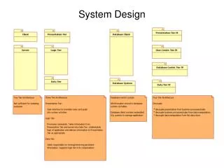
Layers • Consider system environment information to help evolve the analysis model • Smalltalk’s Model-view-controller (MVC) architecture • Model: application logic • View: output logic for the user interface • Control: input logic for the user interface • Separating application logic from user interface logic
5 Layers • Foundation • Problem Domain • Data Management • Human-Computer Interaction • Physical Architecture
Package • A general construct that groups units together • Used to reduce complexity of models • A package diagram shows packages only
Building Package Diagrams • Set the context • Cluster classes together based on shared relationships • Model clustered classes as a package • Identify dependency relationships among packages • Place dependency relationships between packages
Custom Development • Allows for meeting highly specialized requirements • Allows flexibility and creativity in solving problems • Easier to change components • Builds personnel skills • Drawbacks • May tax firm’s resources • May add significant risk
Packaged Software • Software already written • May be more efficient • May be more thoroughly tested and proven • May range from components to tools to whole enterprise systems • Must accept functionality provided • May require change in how the firm does business • May require significant “customization” or “workarounds”
System Integration • The process of combining packages, legacy systems, and new software • Key challenge is integrating data • Write data in the same format • Revise existing data formats • Develop “object wrappers”
Outsourcing • Hire external firm to create system • May have more skills • May extend existing resources • Never outsource what you don’t understand • Carefully choose vendor • Prepare contract and payment style carefully
Selecting a Design Strategy • Business need • In-house experience • Project skills • Project management • Time frame
The Alternative Matrix • Similar to feasibility analysis • Combines several feasibility analyses into one grid • Revisits technical, economic, and organizational feasibility
Request for Proposals • Description of the system you propose to be built • Vendors, developers, service providers respond with proposals including how they will address needs as well as stating cost and time requirements.
Summary • Verifying and Validating the Analysis Models • Evolving the Analysis Models into Design Models • Packages and Package Diagrams • Design Strategies • Developing the Actual Design