Download
1 / 26
280 likes | 727 Vues
THE IBM 370 FAMILY . By: Nick McAvoy & Kristy Salloum Computer Architecture. IBM 370/360 Architecture. The architecture of IBM system 370/360 is one of the most durable systems of the computer age.

E N D
THE IBM 370 FAMILY By: Nick McAvoy & Kristy Salloum Computer Architecture
IBM 370/360 Architecture • The architecture of IBM system 370/360 is one of the most durable systems of the computer age. • It is undergone two major revisions of the product line and over 30 years of technological change. • Still remains a versatile interface between machine and user.
1964 - system 360 announced Model 20 addressing data acquisition, timeshare, pipelining instructions 1968 - 128 bit floating point, rounding, bit alignment, block multiplexing. 1970 - time of day clock, control registers, 6 general purpose instructions. 1972 - virtual storage, CPU timer, extended control timer, clock comparator, program event recording 1970- system 360 becomes 370 Multi-processing extensions, PSW- key- handling instructions, conditional - swapping instructions. 1978 - load address protection, control instructions 1979 - channel set switching 1981 - dual address space, 26-bit addressing, segment protection, I/O instruction queueing. 1984 - 31 bit addressing, channel subsystem, tracing 1985 - interpretive execution 1986 - vector arithmetic Key Dates in Evolution of 370
History of the 360 system • “ one of the most ambitious projects in the history of the computer industry” • 360 was significant because it was the first line of processors with upward and downward compatibility • along with the fact that it was the first major product line designed for both business and scientific use • It extended to the 370 system and 37 years later continues to be widely used • In order for upward and downward compatibility to be possible, micro programming was used.
Development of System/360/370 • Challenge for the 360/370 architects was to create a suitable addressing strategy. • They looked to increase main memory by two or three orders of magnitude, which would be difficult to do using the direct addressing approach that was current a the time. • The architects developed “base-register offset addressing” to allow 12-bit addresses within a contiguous memory area. • They found that instruction sequences would remain within the necessary memory area in a sufficiently large number of cases to justify this approach.
Development of System/360/370(cont) • In an attempt to use a single architecture to meet the needs of an unprecedentedly large segment of its customers, IBM made large scale efforts to develop compatible peripheral interfaces and software were necessary. • System/360 was designed to be able to handle both decimal and binary formatted information, with both variable-field length and floating-point arithmetic capabilities. • Since scientific users tended to use Fortran and business users tended to use Cobol, IBM designed and developed the PL/l programming language in an attempt to provide a programming bridge between the two communities.
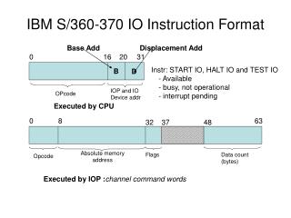
Groups are combined into sets of 8 units which can define 256 different pieces of information. (using binary numbers 0 & 1) Through different combinations of binary numbers, the computer gets its instruction that it is supposed to perform To perform an instruction it is split into two parts. The first part is the opcode and the second is the operand. The opcode tells what operation to perform. The operand contains the address of the data. The computer can execute one instruction at a time. Components of the 370
Components of the 370 (cont.) • In the 370 machines the storage can be one of two states: on or off • The 370 has two groups of instructions: one that uses fixed-length data and the other uses variable-length data.
Variable-length data vs. Fixed-length data • Variable-length: Performs the movement of data from one location in storage to another. • Fixed-length: Uses data that is of specific lengths. These instructions are faster because data is put into certain addresses called integral boundaries. These addresses are evenly divisible by the number of bytes in that particular area.
Virtual Memory • The virtual memory capability, one of system/370’s best, was announced in August 1972. It opted for a 24-bit virtual address. • An appealing argument for virtual memory (dynamic address translation) was the gains in effectiveness that could be expected from programmers once they were relieved of the constraints of conventional methods of planning for memory use. • Not only could the virtual memory provided by translation ease the planning and preparation of software, but it could generalize the utility of programs.
Virtual Memory(cont) • System 370’s virtual memory of 16 megabytes was represented as an area in disk storage. During execution, “pages” of program content were moved on an as-needed basis from disk to memory, or vise versa, by the control program. • This meant that a disk-stored page could be brought to any available page-sized frame in physical memory. This meant that it was no longer necessary to define a separate memory area for each of the programs executed at the same time. • This ensured increased efficiency in the use of memory
Registers in the 370 family • Registers are areas of storage that are set aside in the processing unit. • There are 16 registers in the 370 system. • They are numbered from 0 – 15; generally registers 0,1, and 11-15 are not used because they have other uses.
Registers in MIPS • MIPS is a register-register or load/store architecture, i.e., only loads and stores access memory and all other operations on data are done using the 16 general purpose registers. • The operations and addressing modes are simple-there are about 35 different instruction opcodes, and four addressing modes. • Arithmetic and logical instructions operate on registers or small immediate values. • The Transport operations, Arithmetic and logical operations, and Control transfer operations are assembly language instructions, as well as operations supported directly in the machine.
Registers in MIPS(cont) • Multi-cycle instructions contains those operations that are macro-expanded into several machine-level instructions. • In addition to the 16 general purpose registers, there are two special registers, Hi and Lo, used in the multiply and divide instructions and as a shift amount specifier for variable-length shifts.
Four fields of information • 1) the name field- optional field and must begin with a character from the alphabet; can consist of 8 characters • 2) opcode – mandatory field and must be followed by a blank • 3) operands – usually represent data that could be in main storage, registers, or as part of the instruction itself. • 4) comments – used to clarify instructions • Not every field has to be present and when present a blank is used to separate between each field. No blanks are used within fields.
RR-type- R tells that there is data residing in a register. So in this type there is data in register® SS- type- S tells that that there is data in storage. Here both operands have data in storage SI-type – I tells that the operand consists of immediate data (meaning that the data is in the instruction itself). So in this type the first is a storage location and the second is immediate data. 5 types of Instructions
RX-type – The X also refers to a storage address; however, this specifies actual storage addresses in 3 pieces RS-type – This instruction can have 2 or 3 operands. It depends how many the opcode indicates. If it is 2 the first is a register and the second storage. If it is 3 then the first and second are registers and the third is a storage location. 5 Types of Instructions (cont)
MIPS Instruction Formats • ALU3/ALU2 Two register-register, ALU operations are combined: one is a three operand format assembly instruction (ALU3); the other is a two operand format instruction (ALU2). • Memory Reference/ A load or store operation with a base- ALU2 offset, base-shifted, or base-indexed addressing mode, is combined with a two operand ALU operation. • Memory Reference A load or store using a base-offset with a long offset or a direct address. Load immediate, which includes a 24-bit immediate, is also included in this class.
MIPS Instruction Formats(cont) • Conditional Branch A comparison of two registers determines whether a PC-relative branch is taken. There are also similar trap conditional and set conditional instructions. • Jumps There are four forms of jumps. The effective address for the jump is either absolute or is base-offset. There are both direct and indirect (through memory) jumps using the effective address.
Significance of the 370 system • Known for coining the term “translation-lookaside buffer” • This refers to the important difference between the 370 and 360 which was virtual memory. • One of the biggest problems of architects is computers that run out of address space.
Significance of the 370 (cont) • The “translation-lookaside buffer” keeps track of each address in memory. • According to Hennessey, “Modern machines include a special cache that keeps track of recently used translations.” • This was first seen in the 370 system. • Basically it works when a virtual number gets a hit and then the physical number is used to get an address. • It is often compared to “the cards that are inside the card catalog that are used to look up a set of books in the library.”
Problems with the 370 System • The 370 stored its operating instructions in the semi-conductor memory which meant that whenever the computer was shut off, the memory was erased. • In order to restart the computer, the control program had to be reloaded into memory • The solution to this problem was the invention of the 8 - inch floppy disc that was used to store and ship micro-code.
Success of the 360/370 • System/360/370 served the needs of the customers by reducing their data processing costs and supporting the undertaking of additional applications. • So attractive and successful were the system concepts that others chose to develop 360/370 compatible lines such as RCA’s Spectra 70 series and the Soviet Unions Ryad computers.
Success of the 360/370(cont) • However, a trend during the quarter century following the introduction of the 360/370 was the increasing number of computers designed for users with data processing work loads too limited to make efficient use the generalized input/output capabilities and the extensive instruction set provided by the 360/370 architecture. • By 1989 the large number of small/personal computers accounted for half of the world computer systems and none used the 360/370 architecture.
Success of the 360/370(cont) • However the continued popularity of the system/360/370 was revealed in the higher priced computer systems. • In 1989, a quarter century after the system/360 was introduced, computers based on the 360-370 architecture accounted for more than half of the estimated $260 billion value of these large computers systems installed worldwide. • “Broad acceptance and durability thus joined compatibility and modularity as bases for the abiding importance of the computer architecture first embodied in IBM’s 360 and early 370 systems.”
References Johnson, Palmer, Pugh., IBM’s 360 and Early 370 Systems. The MIT Press. Cambridge, MA., 1991. Rudd, Walter G., Assembly Language. Prentice-Hall. Englewood Cliffs, NY., 1976. Gross, Hennessy, Przybylski, and Rowen., Measurement and Evaluation of the MIPS Architecture and Processor. Stanford University. 1998.\ Hennessy, and Patterson., Computer Architecture: A Quantitative Approach.