Download
1 / 10
100 likes | 270 Vues
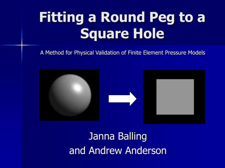
A Method for Physical Validation of Finite Element Pressure Models. Fitting a Round Peg to a Square Hole. Janna Balling and Andrew Anderson. Introduction. Validate subject-specific FE models of the hip using experimental data Single-leg-stance and stair-climbing

E N D
A Method for Physical Validation of Finite Element Pressure Models Fitting a Round Peg to a Square Hole Janna Balling and Andrew Anderson
Introduction • Validate subject-specific FE models of the hip using experimental data • Single-leg-stance and stair-climbing • Cartilage contact stress measured using pressure sensitive film
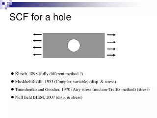
Introduction • Pressure sensitive film • Cut into rosette pattern • Fit to femoral head • Film scanned in 2D • Calibrated • Color intensity is proportional to applied pressure
? Objective • Validate FE model predictions of contact stress with pressure film measurements • Convert 3D FE model pressure plot into a 2D synthetic image • Compare synthetic image with pressure film image
Fit A Sphere • Given d={x,y,z} for n points • Least-Squares Fit Where • Loop origin: (a,b,c) r a= -0.000422081 b= 0.000270402 c= 0.146251 r= 20.5007 only 317 iterations radius: • ao-a ≈ 0 bo-b ≈0 co-c≈0 • else ao=a bo=b co=c • 0 approximation = 2.2204460492503131e-016
y x Transform to Sphere Coordinates • Given d={x,y,z} origin=(a,b,c) radius=r • Surface Point along vector to origin (x,y,z) L (x’,y’,z’) r r x’ x’-a (a,b,c) x-a (0,0,0)
origin center y top top origin -z Transform to Femur Coordinates • Given d={x,y,z} origin=(a,b,c) radius=r center=(cx,cy,cz) top=(tx,ty,tz) • Find Coordinate Transform to origin • Apply To Each Point
(0,0,0) d x L (x,y,z) r σ z y (tx,ty,tz) (x,y,z) β x (0,0,0) y’ (tx,ty,tz) (x’,y’) d β x’ (0,0,0) Transform to Plane Coordinates • Given d={x,y,z} origin=(a,b,c) radius=r center=(0,0,0) top=(tx,ty,tz) • Preserve arc length and x-y orientation .
dx dy bwy bwx Map Plane to JPEG • Given d={x,y} pressure={p(x,y)} resolution=(xres,yres) • Determine Bins and Sample bwx = dx/xres bwy= dy/yres Pressure = average of 3 nearest nodes
Future Work • JPEG Bin assignment • 3 node average • all nodes average • average of 4 corners • transfer function/smoothing • Comparison of JPEG values to film JPEG • bitwise • region • Real Femur FE Mesh • increased complexity • sphere fitting