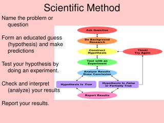
Download
1 / 17
170 likes | 299 Vues
ASIC Development for High S peed S erial D ata T ransmission from Detector F ront -end to the Back -end. Overview. Test results of LOCs1, a 5 Gbps 16:1 serializer. Test results of the LCPLL, a 5 GHz phase-locked-loop Future work: LOCs2 and LOCld. Jingbo Ye

E N D
ASIC Development for High Speed Serial Data Transmission from Detector Front-end to the Back-end Overview. Test results of LOCs1, a 5 Gbps 16:1 serializer. Test results of the LCPLL, a 5 GHz phase-locked-loop Future work: LOCs2 and LOCld Jingbo Ye Department of Physics Southern Methodist University Dallas, TX 75275 yejb@smu.eddu
The purpose and the team • This R&D work is funded by US-ATLAS and IPAS to upgrade the readout of the Liquid Argon Calorimeterfor the High Luminosity LHC. • The work is carried out by the teams of: DataoGong, ChonghanLiu, TiankunLiu, Futian Liang, Annie C. Xiang, and Jingbo Ye (Department of Physics, SMU Dallas, Texas) SuenHou, Da-ShungSu, and Ping-kun Teng (InstituteofPhysics, Academia Sinica, Taipei, Taiwan)
Overview: the Present LAr readout The ATLAS detector Back End Crate 150 m fiber Front End Crate Cryostat The LAr front end electronics box There are 128 chs/FEB, 1524 FEBs read out by the link. Total data rate is over 2Tbps.
Overview: the proposed upgrade • The tentative (upgraded) FEB2 architecture: • Compared with (present) FEB1: • Major requirements on the optical link: • 100 Gbps per FEB data bandwidth with 20% channel redundancy. A total bandwidth of about 150 Tbps. • Low power: 80 W/FEB. Design goal for the link: 20 W. • Radiation tolerant. L1 trigger off FEB: Stream data at 100 Gbps. Parallel fiber optics with redundant channels. Fewer ASICs, simpler design. L1 trigger on FEB: 1.6 Gbps over one fiber. No redundancy. Analog pipeline with associated logic. Total of 11 ASICs and rad-tol qualified COTS.
Overview: concept and ASICs • The Link-on-Chip (LOC) is a concept that we proposed for the upgrade of the ATLAS LAr FEB optical link. • The ASIC technology has been chosen to be a commercial thin-film 0.25 μm silicon-on-sapphire CMOS technology that is suitable for application in the environment of a particle physics detector. • Over time the concept of the transmitting side of the 100 Gbps link has been evolved to be: • MUX is the interface of the link to upstream electronics. • LOCs2 is a 2-lane array serializer. • LOCld is an array laser driver. • For the moment we choose the laser to be a VCSEL. • For the receiving side of the link we plan to use Serdes-embedded FPGAs. There we benefit from the developments in the Versatile Link common project (see poster from Annie Xiang). • The most challenging in this link arethe serializer LOCs2 and the laser driver LOCld. Each fiber channel needs to run at 8-10 Gbps. Details will be discussed later.
Overview: ASIC prototype • To check the serializer design, and to probe the highest speed possible with this SOS technology, we submitted a prototype chip. In this 3 mm × 3 mm tile, we have the following designs: • LOCs1, a 5 Gbps 16:1 serializer. • The LCPLL, a 5 GHz LC VCO based phase locked loop. • The CML driver. • A divide-by-16 circuit. • A varactor, a voltage controlled capacitor. • An SRAM block, designed by INFN Milano. • The chip was submitted for fabrication in Aug. 2009. We received 143 chips at SMU in Nov. 2009. Test setup was prepared during that time window. • Here we report the test results of LOCs1 and the LCPLL.
The 5 Gbps Serializer LOCs1 • LOCs1, design and testing • Ring oscillator based PLL provides clocks up to 2.5 GHz • 16:1 CMOS multiplexer has a tree architecture • 5 Gbps serial data output through a differential CML driver
The 5 Gbps Serializer LOCs1 • LOCs1 test results: 5 Gbps
The 5 GHz LCPLL • Design and test results: • Tuning range: 4.7 to 5 GHz (due to a bug in the design, identified and will be corrected in the future). Simulation: 3.79 to 5.01 GHz. • Power consumption: 121 mW at 4.9 GHz. Compare: ring oscillator based PLL, 173 mW at 2.5 GHz • Random jitter: 1 - 2.5 ps (RMS) • Deterministic jitter: < 17 ps (pk-pk)
Future work: LOCs2 + LOCld • To meet the challenges of a link of 100 Gbps per FEB, we propose: • An array serializer LOCs2 to reduce power dissipation. • An array VCSEL driver LOCldto match with an array of VCSELs. • The design is still in progress and here we report the status. • In design: • 2-ch serializers, 8 Gbps/ch • 4-ch VCSEL driver array, 8 bps/ch • Status: • All fast blocks in CML logic done (green) • Other parts in light green have been verified in LOCs1, under fine tuning. • Single channel VCSEL driver done, move to an array (open drain) driver • The LVDS receiver will need to checked
A few details • The CML Driver has been changed to 5 taps and 3.3V power supply to improve performance in jitter and amplitude. • Tested all high speed CML circuits in a test bench shown below. The overall DJ is about 14 ps (p-p) at typical corner 27 C.
The VCSEL driver • A single channel VCSEL driver operating at 8 Gbps has been developed. • A 4 channel VCSEL driver matching a VCSEL array is under development. Will expand to 12 channel once proved to be successful. Limited by MPW. the schematic of the laser driver (only the last two stages shown) an eye diagram at 8 Gbps based on the post layout simulation
Adjustable Active Peaking • Proposed using an external voltage to adjust the peaking strength. The control will be moved inside the chip in the final version.
Conclusions • We reported the R&D work for ultra fast serial data transmission from detector front-end in particle physics. In this work we actually need to address issues at component level (both ASICs and COTS) and at system implementation level. Reported here is mostly the ASIC work. • A thin-film 0.25 μm Silicon-on-Sapphire CMOS technology has been identified for the ASIC work. • Two prototype designs have been tested to meet design goals. The LCPLL working at 5 GHz points to a feasibility of 8 – 10 Gbps data transmission with this technology. • Design for an array serializer (LOCs2) and an array VCSEL driver (LOCld) are in progress. Some design simulation results shown in this report indicate that the speed of 8 Gbps is achievable. • We rely on progress in industry, such as the PC progress of this SOS technology, and future 180 nm feature size to bring the serial speed to 10 Gbps and beyond. • Adequate support to this research is vital to keep this program viable for future particle physics experiments.
Acknowledgements • We thank US-ATLAS and IPAS/NSC for providing the research funds. We hope that the funds will continue at a proper level for future work. • We are deeply grateful to Paulo Moreira (CERN) for his kind help throughout the design of LOCs1. Without his support, we would not be possible to be here today to talk about this ASIC. • We also would like to thank Fukun Tang, Mauro Citterio, Francesco Lanni and many other collaborators in our community for their kind help and support in this project.
A low power, wide data rate range (1 – 5 Gbps) and rad-tol serializer? • Where are the needs? • What kind of encoding scheme? Would 8b/10b be acceptable? • Can we design one based on LOCs1? • Wide data range achieved by multiple PLLs or by wide tuning range in a single PLL or by logics in the clock fan out unit? Or any other techniques? • Incorporate VCSEL driver in the chip? Or even the VCSEL itself? • We currently do not have the manpower for this design, but would like to help if there are collaborators. Strasbourg April 2011