Download
1 / 44
450 likes | 609 Vues
Wireless LAN Communications. Fundamentals. Radio Frequency Behaviour. Propagation of radio waves Absorption Reflection Scattering Refraction Diffraction Loss Free Space Path Loss Multipath Gain. RADIO WAVES PROPAGATION AND EFFECTS. diffraction. Diffraction. Defined as

E N D
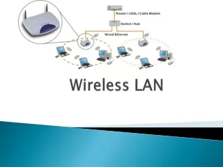
Wireless LAN Communications Fundamentals
Radio Frequency Behaviour • Propagation of radio waves • Absorption • Reflection • Scattering • Refraction • Diffraction • Loss • Free Space Path Loss • Multipath • Gain
RADIO WAVES PROPAGATION AND EFFECTS diffraction
Diffraction • Defined as • the apparent bending of (all) waves around small obstacles • and the spreading out of waves past small openings. • Also: • Applied to EM (radio, light, X-rays) waves traveling through media with different refractive index • Sound waves travelling thru medium of changing acoustic impedance
Diffraction • Diffraction: • When waves pass near a barrier, they tend to bend around the edges of the obstruction
Diffraction • Water flowing around a rock gives an idea of diffraction • Picture Source: Michael Alan’s website
Diffraction • These are cases of diffraction of waves. • The top example shows waves of water being diffracted as they pass thru an opening in a levee. • In the bottom example, an EM wave (light) passes thru a slit or a pin hole and it gets diffracted. • The same principle applies to both cases. • The Pin Hole (or slit) Effect: occurs when waves pass very close to the edge of an object or through a tiny opening, such as a slit or aperture.
Diffraction • Speckle Pattern: • Another example of diffraction. • When a surface is illuminated by a light wave, each point on the illuminated surface acts as a source of (diffracted) secondary spherical waves. • You will see this speckle pattern if you point a laser toward a projection screen or a wall. • Also, speckle pattern appears at the output of optical fibres and that is a type of distortion of the signal.
Reflections • How does reflection happen? • What causes reflection? • What causes sky reflection? • What causes microwave reflection? • Effects and uses of reflections?
Origin of Reflections • Incident EM waves induce small oscillations that polarize the atoms in materials. • This causes the atoms to radiate a secondary wave similar to the incident wave. • Materials, with this atomic structure, reflect waves. • Materials without this atomic structure absorb the waves.
RADIO WAVES PROPAGATION AND EFFECTS radio wave Skyreflections
Layers of the Atmosphere Height from sea level Exosphere • The atmosphere has been classified in layers according to their properties. • The upper layers, thermosphere, mesosphere and exosphere, present a very particular behaviour which is the presence of ionized atoms. • The name of ionosphere is given to this overlaid band of ionized particles 500 KM Thermosphere Ionosphere 80 KM Mesosphere 50 KM Stratosphere Ozone Troposphere Mt. Everest 0 to 10 KM
Sky Reflections • The behaviour of the ionosphere is critical for satellite radio transmission and long range radio communications. • When a radio wave reaches the ionosphere, the electric field of the wave forces the electrons in the ionosphere to oscillate at the same frequency of the radio wave. • Electrons give energy away as recombination or re-irradiation of the same frequency
Sky Reflections • The ionosphere band has been divided into regions: • F region: • F2 region over 210 km • F1 region 140 to 210 km • E region 90 to 140 km • D region 50 to 90 km • The behaviour of these regions depends mostly on the sun rays and the sun activity cycles.
Ionosphere Reflections • D region is present during day time. • D region absorbs or attenuates EM • F2 region is the most important: • It is present 24 hours of the day • highest altitude creates longest reflection paths • Affects the highest HF frequency band
Atmosphere • Atmospheric reflections • LF is reflected by the ionosphere. • MF is reflected by E layer. • HF is reflected by F1, F2 layers. • Source: http://ds9.ssl.berkeley.edu/lws_gems/3/graph_2.htm
Upper Atmosphere Effects • The upper atmospheres layers have a significant effect in certain types of telecommunications. • For example, CB radio or amateur radio uses the reflections to communicate over really long distances. • The layers acts as relays or repeaters pretty much in the same fashion than satellites do.
RADIO WAVES PROPAGATION AND EFFECTS scattering
Scattering • RF waves passing thru a medium are deviated from their original trajectory by the irregularities present in the medium. • The irregularities deviate the waves in random directions
Scattering Rain drops • RF waves passing thru a medium are reflected off the minuscule components of the medium. For example, fog reflection, snow clouds, etc • RF waves get reflected off irregular objects. Typically foliage, chains, fences, rocks, rough surfaces, etc Fog / clouds Foliage Chain fence
Scattering • What is the size of the rhombus in the fence? • Maybe about 10 cm in diameter. • What waves would be affected the most by a chain fence? Chain fence
RADIO WAVES PROPAGATION AND EFFECTS refraction
Refraction • The travelling direction of RF waves gets bended when they pass thru from one medium to another • The media have different density • Similar behaviour as explained by Fresnel law’s of optics
Refraction • The amount of refraction depends on the frequency of the wave. • Some frequencies are more bended than others.
RADIO WAVES PROPAGATION AND EFFECTS Path losses
Free Space Loss • When radio waves propagate thru either space or air, they tend to spread their energy concentration as they move away from the source. • Basically, the wave front dissipates in the space. • Also, the medium (space or air) absorbs the energy. • The result is that the relative strength of the wave weakens when measured at longer distances from the source.
Free Space Loss • Broadening of Beam (dispersion) • Absorption
Free Space Path Loss • The free space path loss have been studied and measured and its behaviour is represented by the equation above. • This equation assumes that free space is the transmission medium. • FSPL in decibels • Frequency in MHz • Distance in kilometres
Free Space Path Loss • FSPL in decibels • Frequency 2412 MHz • Distance in kilometres • Notice: cases that double the distance, like 10 metres to 20 metres or 100 metres to 200 metres Loss (dB) Distance
FSPL • Greater frequencies have more losses • Loss increases with the distance • The behaviour of FSPL is logarithmic • Doubling the distance increases the loss by 6 dB
Path Loss Factor metres metres N factor (see next table) • Alternatively, this equation is used when the medium is not necessarily free space. • Wavelength (Lambda) is in metres. • Distance is in metres. • N is a factor that depends on the medium.
Typical Losses Caused by Obstacles • Drywall = -3 dB • Glass = - 3dB • Wood = - 3 dB • Metallic structure = - 10 dB • Brick wall = – 15 dB
Free Space Loss • Calculate: • Free Space n = 2 • Distance 1000 metres or 1 KM • Frequency 2412 MHz or wavelength 0.12 metres • Use both equations and compare results:
Free Space Loss • Calculate (using both formulas): • Free Space n = 2 • Distance 1000 metres or 1 KM • Frequency 2412 MHz or wavelength 0.12 metres • Same result! • It is easier to use the first formula when the calculation is intended for Free Space Environment • The second formula is better for any other kind of environment
Free Space Loss • For FREE SPACE LOSS (n=2) the equation… • …can be simplified, using the multiplication property of logarithms, to: • We use the term FREE SPACE loosely here, since we also apply this equation to AIR since RF propagates in the air at 99.99% of C.
Summary for Free Space Loss (and air) • Use either one of these equations to calculate LOSS caused by propagation thru Free Space and Air • If you have the frequency use equation 1 (top) • If you have wavelength equation 2 is easier (bottom)
Path Loss Calculations exercises
Calculate PL • CRTC assigns the following frequencies for microwave links between the sites: • Oakville-Brampton: • TX: 3.2 GHz • RX: 5.2 GHz • Oakville-Mississauga: • TX: 4.0 GHz • RX: 6.0 GHz • Mississauga-Brampton: • TX: 15 GHz • RX: 18 GHz 9.96 KM 15.7 KM 21.1 KM
Calculate PL • Path Losses • Oakville-Brampton: • TX: 129 dB @ 3.2 GHz • RX: 133.25 dB @ 5.2 GHz • Oakville-Mississauga: • TX: 128.4 dB @ 4.0 GHz • RX: 131.9 dB @ 6.0 GHz • Mississauga-Brampton: • TX: 135.9 dB @ 15 GHz • RX: 137.5 dB @ 18 GHz 9.96 KM 15.7 KM 21.1 KM
Calculate PL • CRTC assigns the following frequencies for microwave links between the sites: • CN Tower-Oakville: • TX: 3.2 GHz • RX: 5.2 GHz • CN Tower-Mississauga: • TX: 4.0 GHz • RX: 6.0 GHz • CN Tower-Brampton: • TX: 15 GHz • RX: 18 GHz 28.4 KM 22.2 KM 31.8 KM
Calculate PL • CRTC assigns the following frequencies for microwave links between the sites: • CN Tower-Oakville: • TX: 132.6 dB @ 3.2 GHz • RX: 136.8 dB @ 5.2 GHz • CN Tower-Mississauga: • TX: 131.4 dB @ 4.0 GHz • RX: 134.9 dB @ 6.0 GHz • CN Tower-Brampton: • TX: 145 dB @ 15 GHz • RX: 146.6 dB @ 18 GHz 28.4 KM 22.2 KM 31.8 KM
Summary • Radio waves propagation is intrinsically affected by the transmission medium which typically is air or vacuum. • Obstacles in the path of radio waves also affect the propagation in various ways. • Knowledge of these phenomena is required by the radio professional.