Download
1 / 20
200 likes | 211 Vues
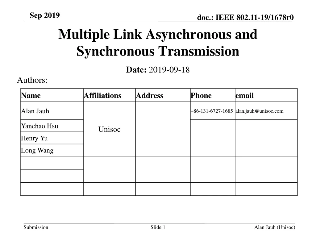
Multiple Link Asynchronous and Synchronous Transmission. Date: 2019-09-18. Authors:. Introduction. In multiple link transmission, the asynchronous mode has better performance compared to synchronous mode

E N D
MultipleLinkAsynchronous and Synchronous Transmission Date: 2019-09-18 Authors: Alan Jauh (Unisoc)
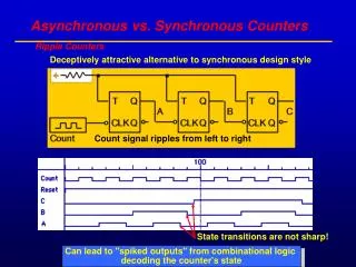
Introduction • In multiple link transmission, the asynchronous mode has better performance compared to synchronous mode • When the isolation between two links is not good enough, the TX in one link will have significant interference to the other link. In this case, asynchronous transmission is not possible and synchronous mode is required • We propose a mixed asynchronous and synchronous transmission mode Alan Jauh (Unisoc)
Asynchronous vs. Synchronous • Asynchronous: • In an asynchronous multiple links mode, the transmission between links is independent • Synchronous: • Several links in a synchronous mode form a synchronous group • The transmission in a synchronous group is synchronized • “Synchronized” means to avoid simultaneous TX and RX within a synchronous group • The backoff process is TBD. In a single primary case, the backoff process is in primary link Alan Jauh (Unisoc)
Primary Channel in Synchronous Mode • Single primary channel and Multiple primary channels have been proposed. • The proposed mixed synchronous and asynchronous solution do not have the limitation on the number of primary channels in a synchronous group • Single primary channel in a synchronous group is slightly preferred due to • The operation is similar to 80+80 mode and the interoperability is proved Alan Jauh (Unisoc)
Mixed Synchronous & Asynchronous Configuration • A synchronous group can be an asynchronous multiple link element, (here use primary link to represent the synchronous group) e.g. • A multiple links system is configured having links A, B, C and D • The isolation between link B and link C is not good enough, so link B and link C form a synchronous group and link B is the primary link • In this case, the transmission between link A, B, D is asynchronous • Link C is the secondary link of a synchronous group with primary link B. The transmission of link C will be based on the primary link B Alan Jauh (Unisoc)
Mixed Synchronous & Asynchronous Configuration Example • Asynchronous between Link A,B,D • Link B,C in the same Synchronous group. Link B is the Primary link, Link C is secondary link AP MAC LMAC2 LMAC3 LMAC1 LMAC4 PHY2 PHY3 PHY1 PHY4 Link D Link C Link A Link B Synchronous group Primary link PHY1 PHY2 PHY3 PHY1 PHY2 LMAC1 LMAC2 LMAC3 LMAC1 LMAC2 MAC MAC Synchronous Primary link B Asynchronous STA1 STA2 Alan Jauh (Unisoc)
Mixed Synchronous & AsynchronousConnection • Multiple asynchronous links can form a virtual synchronous group and connect to a synchronous group. E.g.,a multiple links device having asynchronous links A and B can connect to • Devices with asynchronous links A and B (pure asynchronous connection) • Devices with a synchronous group where primary link is link A and secondary link is link B (mixed connection) • Devices with a synchronous group where primary link is link B and secondary link is link A (mixed connection) Alan Jauh (Unisoc)
Mixed Synchronous & AsynchronousConnection Example (1/) AP Asynchronous MAC • The transmission between AP and STA2 is asynchronous • The transmission between AP and STA1 is synchronous • AP cannot use ch2 only to send data to STA1 • AP can use ch1 only to send data to STA1. If the channel is also idle in ch2, then AP can use ch1+ch2 to send data to STA1 LMAC2 LMAC1 Synchronous group PHY2 PHY1 Ch 1 Primary link Ch 2 Asynchronous PHY1 PHY2 PHY1 PHY2 LMAC1 LMAC2 LMAC1 LMAC2 MAC MAC Synchronous Primary link ch1 STA1 STA2 Alan Jauh (Unisoc)
Mixed Synchronous & AsynchronousConnection Example (2/) • The transmission between AP and STA1 are synchronous • AP cannot use ch2 only to send data to STA1 • AP can use ch1 only to send data to STA1. If the channel is also idle in ch2, then AP can use ch1+ch2 to send data to STA1 AP Asynchronous MAC LMAC2 LMAC1 Synchronous group PHY2 PHY1 Ch 1 Primary link Ch 2 • The transmission between AP and STA2 are synchronous • AP cannot use ch1 only to send data to STA2 • AP can use ch2 only to send data to STA2. If the channel is also idle in ch1, then AP can use ch2+ch1 to send data to STA2 PHY1 PHY2 PHY1 PHY2 LMAC1 LMAC2 LMAC1 LMAC2 MAC MAC Synchronous Primary link ch1 Synchronous Primary link ch2 STA1 STA2 Alan Jauh (Unisoc)
Other Asynchronous/Synchronous Mixed Multiple Links Coexistence Examples (1/) Asynchronous AP MAC LMAC2 LMAC3 LMAC1 LMAC4 PHY2 PHY3 PHY1 PHY4 Ch2 Ch4 Ch3 Ch1 Synchronous group Primary link PHY1 PHY2 PHY3 PHY1 PHY2 LMAC1 LMAC2 LMAC3 LMAC1 LMAC2 MAC MAC Synchronous Primary link ch2 Synchronous Primary link ch4 STA1 STA2 Alan Jauh (Unisoc)
Other Asynchronous/Synchronous Mixed Multiple Links Coexistence Examples (2/) Asynchronous AP MAC LMAC2 LMAC3 LMAC1 LMAC4 PHY2 PHY3 PHY1 PHY4 Ch2 Ch4 Ch3 Ch1 Synchronous group Primary link PHY1 PHY2 PHY3 PHY1 PHY2 LMAC1 LMAC2 LMAC3 LMAC1 LMAC2 MAC MAC Synchronous Primary link ch2 Asynchronous STA1 STA2 Alan Jauh (Unisoc)
Conclusion • Asynchronous multiple links system can have better performance but need good isolation between links • Synchronous multiple links system can avoid the requirement of isolation between links, although the performance is worse • Besides pure synchronous/asynchronous configuration/connection, we may also need to support mixed configuration/connection • We propose a mixed multiple links system that can support mixed configuration and mixed connection Alan Jauh (Unisoc)
References [1] 11-19/760r1 Multi-band Opinion • [2] 11-19/1116r1 Channel Access in Multi-band operation • [3] 11-19/1144r1 Channel Access for Multi-link Operation • [4] 11-19/0821r0 Multiple Band Operation Discussion Alan Jauh (Unisoc)
Straw Poll #1 • Do you agree to support mixed synchronous & asynchronous configuration in TGbe multiple links operation • Y: • N: • A: Alan Jauh (Unisoc)
Straw Poll #2 • Do you agree to support mixed synchronous & asynchronous connection in TGbe multiple links operation • Y: • N: • A: Alan Jauh (Unisoc)
Backup Slides Alan Jauh (Unisoc)
Fairness inAsynchronous/Synchronous Mixed Mode • Definition: • Primary link data: the data that can be sent out without further constraint on other link • Secondary link data: the data that can be sent out together with its corresponding primary link data • Asynchronous transmission data can be treated as primary link data • For a synchronous transmission, when its primary link data get the TXOP, if there is other primary link data in front of its secondary link queuing list, the transmission in secondary link is not allowed Alan Jauh (Unisoc)
Mixed Multiple LinksFairness Example(1/) Asynchronous AP MAC LMAC2 LMAC1 Synchronous group PHY2 PHY1 Ch 2 Ch 1 Primary link Asynchronous PHY1 PHY2 PHY1 PHY1 PHY2 LMAC1 LMAC2 LMAC1 LMAC1 LMAC2 MAC MAC MAC Synchronous Primary link ch1 STA3 STA1 STA2 Alan Jauh (Unisoc)
Mixed Multiple LinksFairness Example(2/) ... • In this example, ch1 and ch2 has transmit opportunity in a round robin manner. The transmission sequence is as below: • A1 in ch1 • A2 in ch2 • B1 in ch1 and B2 in ch2 synchronously (ch2 is also idle) Descriptors C1(2) B2(P1S2) Synchronous B1(P1S2) A2(1,2) Asynchronous A1(1,2) When ch2 is also idle, B2 can be sent with B1 Dispatch ... ... C1 Channel 1 queuing list Channel 2 queuing list B2 Assigned links B2(S) B1 B1(S) sequence A2 A2 Destination A1 A1 Ks(i,j) Alan Jauh (Unisoc)
Mixed Multiple LinksFairness Example(3/) ... • In this example, ch1 and ch2 has transmit opportunity in a round robin manner. The transmission sequence is as below: • A1 in ch1 • A2 in ch2 • B1 in ch1 (in ch2 queuing list, C1 and C2 are in front of B1 and B2, no secondary transmission to B) • C1 in ch2 Descriptors B2(P1S2) Synchronous B1(P1S2) C2(2) Single link C1(2) A2(1,2) Asynchronous A1(1,2) B2 cannot be sent with B1 since there are C1, C2 in front of it Dispatch ... ... B2(S) B1(S) Channel 1 queuing list Channel 2 queuing list Assigned links C2 B2 C1 B1 sequence Destination A2 A2 Ks(i,j) A1 A1 Alan Jauh (Unisoc)