Download
1 / 13
130 likes | 334 Vues
KEB COMBIVERT F5-M Exercises. Exercise 1. Startup / Speed-controlled Operation. Start up the servo amplifier and parameterize the unit so that it fulfills the following requirements:. Speed range 0...3000 rpm. Setpoint input ± 10 V via PLC.

E N D
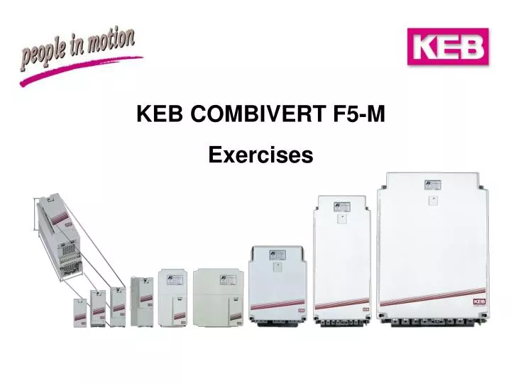
KEB COMBIVERT F5-M Exercises
Exercise 1 Startup / Speed-controlled Operation Start up the servo amplifier and parameterize the unit so that it fulfills the following requirements: • Speed range 0...3000 rpm • Setpoint input ± 10 V via PLC • The ramps are generated by the PLC; the inverter must follow as exactly as possible. • For a manual setting-up operation it shall be possible to drive a speed of 50 rpm • in both directions. • The torque limitation shall be adjusted to 200% of the rated motor torque. • There is one limit switch for each direction of rotation. Reaching one of these limit switches shall trigger a quick stop. Afterwards the modulation shall be switched off and digital output D2 shall become active; restart only after a reset. • Via a digital input it shall be possible to trigger a quick stop; afterwards a • holding torque shall be raised; new start after reset Prepare a parameter list and a terminal connecting plan for this exercise. Measure an acceleration process up to 3000 rpm and the time required for it!
Exercise 2 Speed-controlled Operation For a hoist axis the following requirements shall be fulfilled: • The speed is adjusted by a 0...10 V signal in a range of 0...2400 rpm; the direction of rotation is given by two digital inputs. • The max. speed (2400 rpm) shall be reached in 1.2 sec.; the jerk at starting and stopping should be reduced by S-shaped ramps. • The mechanical brake (release and close-time 100 ms) is controlled by a relay output. • A transistor output shall provide a „ready“-signal to the PLC. • The speed controller has to be very stiff at zero speed to get a good take-over of the load when the brake opens. • The pulses from the encoder have to be transferred to the PLC divided by the factor 2. Prepare a parameter list and a terminal connecting diagram for this exercise and check the speed and the brake control with the oscilloscope!
Exercise 3 Torque-controlled Operation Parameterize the servo amplifier so that the following requirements of a winding drive are fulfilled: • The following operating mode shall be adjustable via digital input I3: • 1.) I3 enabled => torque control in the range 0...200% of the rated motor torque • 2.) I3 disabled => standstill / manual setting-up operation (jog speed) • In manual setting-up operation I1 shall trigger a speed of +30 rpm; I2 shall trigger a speed of -30 rpm. • The torque is preset with a ± 10 V - signal via REF1; the speed shall be limited by a 10 V - signal within the range of 0...2000 min-1 • The speed shall be represented by an analog output, ± 10 V shall correspond to the speed of ± 2000 min-1. Prepare a parameter list and a terminal connecting diagram for this exercise and check the torque control with the oscilloscope!
Exercise 4 Speed Synchronous Operation Parameterize the servo amplifier so that the following requirements of a drafting system are fulfilled: • The master speed nMaster shall be adjustable in the range of 0... 2000 rpmvia a potentiometer.The gear transmission ratio of the slave speed shall be preset to 95 % of nMaster; limit switches do not exist. • The torque limit of the slave-drive shall be adjustable in the range of 0...200% of the rated motor torque via a potentiometer („quasi-slipping clutch“). • On reaching this torque limit the digital output D1 shall be activated. • It shall be possible to switch off the speed synchronous operation via digital input I3. In this case the slave-drive shall stand still and can only be moved by way of the jog-speed inputs with +/-50 min-1. • The slave torque shall be represented by analog output 1. 10 V shall correspond to the double rated motor torque. Prepare a parameter list and a terminal connecting diagram for the slave drive and check master and slave drive with the oscilloscope!
Exercise 5 Angular Synchronous Operation Parameterize the servo amplifier so that the following requirements are fulfilled: • The master speed nMaster shall be adjustable by pot. in the range of 0... 2000 min-1.The slave drive shall follow angular synchronous 1:1 in the opposite sense of rotation. • If a phase-angle error of more than 10° occurs for more than 500 ms the digital output D1 shall be activated. • The inputs I5 and I6 serve as limit switches (NC contact), the left switch serves as a reference switch at the same time. The reference mode shall be started via input I4 with 50 min-1 (stop directly at the reference switch). • It shall be possible to deactivate the synchronous operation via I3 for manual operation with ± 10 V = ± 2500 min-1. Prepare a parameter list for the slave drive and check master and slave with the oscilloscope!
Exercise 6 Positioning Parameterize the servo amplifier so that the following requirements of a rotating table are fulfilled: • Positioning steps of 45°, 15° and 2,5° shall be triggered via the 3 digital inputs I1, I2 and I3. The gear transmission ratio nMotor /nTable is 72. The triggering of the positioning steps shall directly take place on activating the inputs. • The positioning steps shall be carried out with 300 ms ramps and a maximum speed of 1500 rpm. • On reaching the target position (± 200 incr.) digital output D1 shall be activated. • A reference point approach shall be triggered via input I5 (200 rpmcounter-clockwise rotation). The reference switch is connected to I6. The stopping point shall be on the right hand side of the reference switch. • For manual operation with ± 10 V = ± 1500 rpmit shall be possible to switch off the positioning mode by another digital input. Prepare a parameter list and check the positioning with the oscilloscope.
Exercise 6a Positioning A linear axis shall fulfill the following requirements: • By means of 3 digital inputs (I1, I2, I3) the absolute positions +100.000 incr., +20.000 incr. and +5.000 incr. shall be selectable. The positioning shall be started by a pulse on input I4. • The approaching of the positions shall take place with max. 2500 rpm; the torque is to be limited to the triple rated motor torque and the ramps shall be so long that the motor can follow with a max. angular deviation of 20°. • At the first pulse on I4 the reference point approach shall be triggered (50 rpm). The reference switch which is the left limit switch at the same time is connected to I6, the right limit switch is connected to I5. The reference run shall stop at the zero pulse, which is defined as position 0 incr. • On reaching a target position digital output D1 shall be activated. • If none of the inputs I1, I2, I3 is active, the drive shall keep its position. Prepare a parameter list and check the positioning with the oscilloscope!
Exercise 6b Positioning A form feed drive on a woodworking machine shall fulfill the following requirements: • A pulse at input I2 shall start the drive with a speed of 2000 rpm in forward direction. • On reaching a proximity switch which is connected to the input I1 a residual positioning step with 30 revolutions at the motor shaft shall be triggered. • The ramps for the residual positioning and the max. torque should be adjusted so that there is no overshoot at the stopping point. • There is neither a reference switch nor any limit switch. • On reaching the target position digital output D1 shall be activated. • A manual movement (jog-speed) with 50 rpm in both directions shall be possible by the digital inputs I3 and I4. Prepare a parameter list and check the positioning with the oscilloscope!
Exercise 7 Positioning A linear axis shall fulfill the following requirements: • The absolute positions +200.000 incr., +100.000 incr., +50.000 incr., +20.000 incr., +5.000 incr. and 0 incr. shall be driven sequentially. Each positioning step shall be started by a new pulse at input I1. • The approaching of the positions shall take place with max. 1500 rpm and the ramps shall be so long that the motor can well follow. • I2 shall start the reference run (150 rpm). The reference switch which is the left limit switch at the same time is connected to I6, the right limit switch is connected to I5. The reference run shall stop at the zero pulse, which is defined as position 0 incr. The zero pulse shall be supervised during the reference run. • After finishing the reference run the digital output D1 shall be activated. On faults or reaching a limit switch the output D2 shall become active. Prepare a parameter list and check the positioning with the oscilloscope!
Exercise 7a Positioning A form feed drive shall fulfill the following requirements: • By a starting pulse at digital input I3 the absolute positions +1.455.000 incr., +256.000 incr. and +920.000 incr. shall sequentially be approached. Afterwards the drive shall stand still (modulation on) and wait for the next starting pulse. • The approaching of the positions shall take place with max. 2000 min-1; the torque is to be limited to 150% of the rated motor torque and the ramps shall be as short as possible. • A pulse at I1 shall start the reference point run (250 rpm). The reference switch is connected to I2 and the reference position is defined as 0 incr. After having completed the reference run the drive shall automatically drive on to position +50.000 incr. • It shall be possible to switch off the positioning mode by the digital input I4. Prepare a parameter list and check the positioning with the oscilloscope!
Exercise 8 Time-controlled Positioning A servo axis shall fulfill the following requirements: • When digital input I3 is active the absolute positions +100.000 incr. and +50.000 incr. shall be approached alternately. There shall be a pause of 200 ms between each positioning step; the clock-pulse rate shall be as high as possible. • A reference run (80 rpm) shall be triggered via I6. The reference switch (NC contact) is connected to I5. The reference mode shall stop on the zero pulse, which is defined as position 0 incr. Limit switches do not exist. • When the positioning mode is interrupted by I3 it shall be possible to activate a jog speed of ± 50 rpm by means of two digital inputs. Prepare a parameter list and check the positioning with the oscilloscope!
Exercise 9 Positioning + Synchronous Running A drive at a flying saw shall be parameterized in the following way: • A pulse at input I2 shall run the drive synchronously to the master (master speed = 1000 rpm, speed ratio 1:1). During the operation this pulse must automatically be generated each time when the starting position is reached. • On reaching a proximity switch which generates a signal for input I1 the drive shall run back to the starting position with 1500 rpm; this starting point shall be 360° in front of the reference point. • The reference run shall be triggered by input RST (100 rpm; stop at the zero pulse). The reference switch is the left limit switch at the same time (NC contact) and is connected to input I6. The right limit switch is connected to I5. After ending the reference run the transistor output D2 shall be enabled. • A jog speed of ± 100 rpm shall be enabled by the inputs I3 and I4. Prepare a parameter list and check the movement with the oscilloscope!