Download
1 / 70
720 likes | 819 Vues
Gain insight into the network layer & IP addressing in the Internet. Explore IPv4 and IPv6, IP headers, protocols & subnetting essentials.

E N D
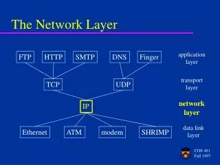
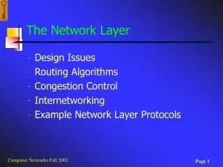
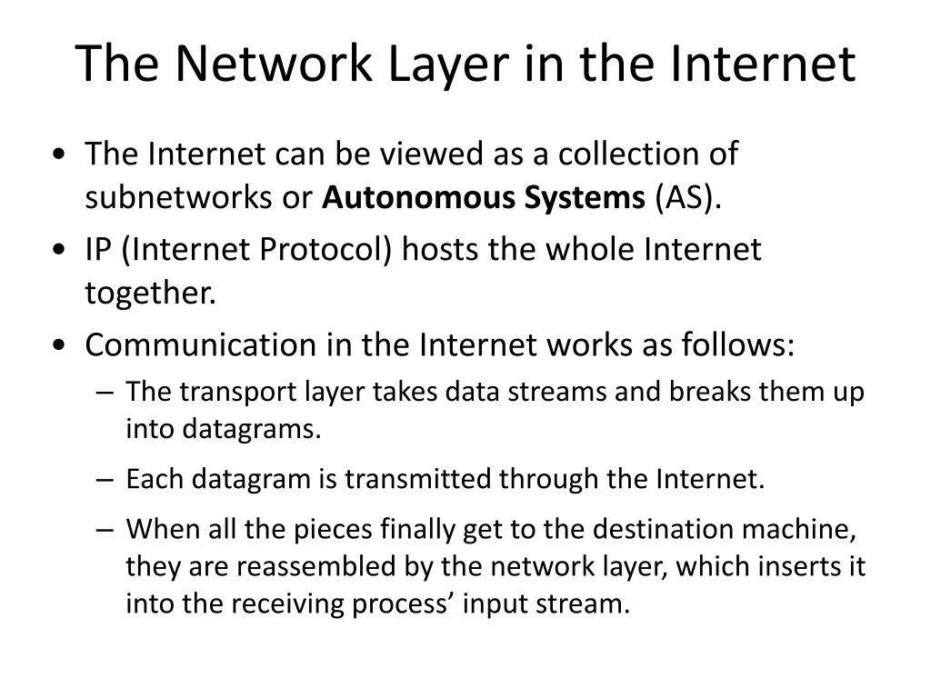
The Network Layer in the Internet • The Internet can be viewed as a collection of subnetworks or Autonomous Systems (AS). • IP (Internet Protocol) hosts the whole Internet together. • Communication in the Internet works as follows: • The transport layer takes data streams and breaks them up into datagrams. • Each datagram is transmitted through the Internet. • When all the pieces finally get to the destination machine, they are reassembled by the network layer, which inserts it into the receiving process’ input stream.
IP Addresses • IP addresses are the most common logical addresses. (Everyone on the Internet has one.) • 32 - bit numbers (IP version 4) • 32 - bits yields 232 unique numbers • 232 =4,294,967,296 • there are over 4 billion possible IPv4 addresses • but many are “wasted” due to the allocation scheme
IPv6: The Next Generation The newest version of IP (version 6, or IPng) uses 128 bits, yielding 2128unique combinations That’s over 340,000,000,000,000,000,000,000,000,000,000,000,000 possible addresses! • IPv6 is slowly be integrated in the existing Internet. • IPv4’s 32 bits continues to be the dominant form of IP addressing.
The IP Header -V4 The IPv4 (Internet Protocol) header.
IPv4 Header Format • Version – The IP version number, 4. • Header length – The length of the datagram header in 32-bit words. • Type of service – Contains five subfields that specify the precedence(priority 0-7), delay, throughput, reliability, and cost desired for a packet. • Total length – The length of the datagram in bytes including the header, options, and the appended transport protocol segment or packet. The maximum length is 65535 bytes. • Identification – An integer that identifies the datagram. • DF – Don’t fragment
IPv4 header format • MF – More Fragments. All fragments except the last one have this bit set. • Fragment offset – The relative position of this fragment measured from the beginning of the original datagram in units of 8 bytes. • Time to live – How many routers a datagram can pass through. Each router decrements this value by 1 until it reaches 0 when the datagram is discarded. This keeps misrouted datagrams from remaining on the Internet forever. • Protocol – The high-level protocol type.
IPv4 header format • Header checksum – A number that is computed to ensure the integrity of the header values. • Source address – The 32-bit IPv4 address of the sending host. • Destination address – The 32-bit IPv4 address of the receiving host. • Options – A list of optional specifications for security restrictions, route recording, and source routing. Not every datagram specifies an options field. • Padding – Null bytes which are added to make the header length an integral multiple of 32 bytes as required by the header length field.
The IP Protocol Some of the IP options. 5-54
IP Addresses • Traditionally, IP addresses were divided into the five categories: A, B, C, D, E. • Network numbers are managed by a nonprofit corporation called ICANN (Internet Corporation for Assigned Names and Numbers) to avoid conflicts. • Network address, which are 32-bit numbers, are usually written in dotted decimal notation.
IP Addresses IP address formats.
"Classful" Addressing Class Determination Algorithm • If the first bit is a “0”, it's a class A address and we're done. (Half the address space has a “0” for the first bit, so this is why class A takes up half the address space.) If it's a “1”, continue to step two. • If the second bit is a “0”, it's a class B address and we're done. (Half of the remaining non-class-A addresses, or one quarter of the total.) If it's a “1”, continue to step three. • If the third bit is a “0”, it's a class C address and we're done. (Half again of what's left, or one eighth of the total.) If it's a “1”, continue to step four. • If the fourth bit is a “0”, it's a class D address. (Half the remainder, or one sixteenth of the address space.) If it's a “1”, it's a class E address. (The other half, one sixteenth.)
Hosts for Classes of IP Addresses Class A (24 bits for hosts) 224 - 2* = 16,777,214 maximum hosts Class B (16 bits for hosts) 216 - 2* = 65,534 maximum hosts Class C (8 bits for hosts) 28 - 2* = 254 maximum hosts * Subtracting the network and broadcast reserved address
IP Addresses Special IP addresses.
Subnets A campus network consisting of LANs for various departments.
Subnetting • Division of a network into subnets • For example, division of a Class B address into several Class C addresses • Some of the host IDs are used for creating subnet IDs. • Use parts of the host IDs for subnetting purpose • A subnet mask is used to facilitate the flow of traffic between the different subnets and the outside network (hops). • A hop is the distance a data packet travels form one node to the other
Routing of Traffic 140.15.1.0 1 Routing 140.15.0.0 140.15.2.0 2 140.15.3.0 Outside world 3 Subnets
Subnet Configuration Subnet ID 140 15 1 0 ….. 140 15 1 1 140 15 1 254 First Host ID Last Host ID
Subnetting Example • Consider the case of a class C address 195. 175.25.0 assigned to an organization • Subnets can be constructed by allocating part of the higher-order bits of the host ID • Assume that three of the higher-order bits of the host ID are to be reserved for that purpose
Subnetting Structure 195 175 25 0 11100000 Subnet Mask
Usable Subnets (6)
Sample Subnet Division Subnet 1 Subnet 2 195.175.25.32 195.175.25.64 Router 195.175.25.33 . . . 195.175.25.62 195.175.25.65 . . . 195.175.25.94 30 hosts per subnet.
Overview of the Masking Process • IP address and subnet masks are used for the masking operation • The purpose of masking is to identify whether an IP address corresponds to a local host or a remote host • The mathematical technique used is known as the ANDing process
Subnet Masking Example • Subnet ID: 195.175.25.32 • Subnet Mask: 255.255.255.224 • Host address • 195.175.25.34 • Case 1 destination address • 195.175.25.40 • Case 2 destination address • 195.175.25.67
Network Scenario Outside World Local Host 195.175.25.40 Router Subnet Mask: 255.255.255.224 Host 195.175.25.34 195.175.25.40 195.175.25.67
Computing Subnet ID at Startup Yields subnet ID.
TCP/IP Properties of the Host
Masking of Destination Address:Case 1 Yields subnet ID to be that of the local subnet.
Case 1 Forwarding of Data Packets • The destination host is local • Broadcast for the hardware address of the local host at IP 195.175.25.40 • Send information to the local host
Masking of Destination Address:Case 2 Yields subnet ID to be that of different subnet.
Case 2 Forwarding of Data Packets • The destination host is remote • Send information to the gateway • The router at the gateway will route the data packet to the appropriate subnet
Summary of Transmission and Routing of Data Packets Subnet at 195.175.25.64 Local Host 195.175.25.40 Router Subnet Mask: 255.255.255.224 Host 195.175.25.34 195.175.25.40 (Case 1) 195.175.25.67 (Case 2)
Subnet mask • For example, use a 6-bit subnet number and a 10-bit host number. The subnet mask is 255.255.252.0 or /22. • Subnet addresses: 156.26.4.1, 156.26.8.1, 156.26.12.1, etc. A class B network subnetted into 64 subnets.
Supernetting • Subnetting allows an organization to share a single IP network address among multiple physical networks • Supernetting (a.k.a. classless addressing) allows the addresses assigned to an organization to span multiple IP network addresses
CIDR—Classless InterDomain Routing • For most organizations, a class A network, with 16 million addresses is too big, and a class C network, with 256 addresses is too small. A class B network, with 65,536, is just right. • In Internet folklore, this situation is known as the three bears problem. • The basic idea behind CIDR, is to allocate the remaining IP addresses in variable-sized blocks, without regard to the classes. • If a site needs, say, 2000 addresses, it is given a block of 2048 addresses on a 2048-byte boundary. • If need 8000 hosts, then allocate a block of 8192 addresses, i.e., 32 contiguous class C networks.
How a large number of IP addresses are wasted using IPv4 address classes? • If a network has slightly more number of hosts than a particular class, then it needs either two IP addresses of that class or the next class of IP address. • For example, let use say a network has 300 hosts, this network needs either a single class B IP address or two class C IP addresses. • If class B address is allocated to this network, as the number of hosts that can be defined in a class B network is (2^16 - 2), a large number of host IP addresses are wasted. • If two class C IP addresses are allocated, as the number of networks that can be defined using a class C address is only (2^21), the number of available class C networks will quickly exhaust. • Because of the above two reasons, a lot of IP addresses are wasted and also the available IP address space is rapidly reduced
CIDR: classless interdomain routing Suppose an organization is allocated four contiguous class C networks: 205.100.0.0, 205.100.1.0, 205.100.2.0, 205.100.3.0. Question: how to treat these four contiguous networks as one from outside? Network mask which will mask out one common prefix for these four networks. Question: what is the network mask for these four networks? 205.100.0.0 --- 11001101 . 01100100 . 00000000 . 00000000 205.100.1.0 --- 11001101 . 01100100 . 00000001 . 00000000 205.100.2.0 --- 11001101 . 01100100 . 00000010 . 00000000 205.100.3.0 --- 11001101 . 01100100 . 00000011 . 00000000 The common prefix: 11001101 . 01100100 . 000000 Therefore, network mask: 11111111 . 11111111 . 111111 00 . 00000000, i.e., 255.255.252.0 In routing table, instead of putting all four networks entries, just put one entry: 205.100.0.0/22, where 22 indicates the network mask is 22 bits. CIDR is also called supernetting because it “supernets” multiple networks into one.
CDR – Classless InterDomain Routing A set of IP address assignments. 5-59
Private Network • Private IP network is an IP network that is not directly connected to the Internet • IP addresses in a private network can be assigned arbitrarily. • Not registered and not guaranteed to be globally unique • Generally, private networks use addresses from the following experimental address ranges (non-routable addresses): • 10.0.0.0 – 10.255.255.255 • 172.16.0.0 – 172.31.255.255 • 192.168.0.0 – 192.168.255.255 Note :Check http://10.45.10.4/
Network Address Translation (NAT) • NAT is a router function where IP addresses (and possibly port numbers) of IP datagrams are replaced at the boundary of a private network • NAT is a method that enables hosts on private networks to communicate with hosts on the Internet • NAT is run on routers that connect private networks to the public Internet, to replace the IP address-port pair of an IP packet with another IP address-port pair.
Basic operation of NAT • NAT device has address translation table
NAT – Network Address Translation Placement and operation of a NAT box.
Internet Control Message Protocol • The control messages • destination unreachable • time exceeded: TTL zero, (wandering to too long) • parameter problem: header invalid • source quench, too much packets (choke packet) • fragmentation required: MTU too small. • for information messages: • echo request/reply • timestamp request/reply • Two programs that use the ICMP protocol: • ping and traceroute • IP invokes ICMP to report errors.
Internet Control Message Protocol The principal ICMP message types. 5-61
How a host determines its IP address? • A host determines its IP address during the boot-up process either from a configuration file stored in the local hard disk of the system or • using a network protocol like RARP, DHCP, BOOTP from the servers in the network.
ARP– The Address Resolution Protocol • ARP: Address Resolution Protocol • find out the Ethernet address for an IP address • a host broadcast to everyone asking “who owns IP address xxx.xxx.xxx.xxx” • The host with that IP address response with its Ethernet address. • RARP: Reverse Address Resolution Protocol • Find out a host’s IP address. • The host broadcast to everyone asking “My Ethernet address is xx:xx:xx:xx:xx:xx, who knows my IP address?” • The RARP server looks up the configuration file and reply with its IP address.
Dynamic Host Configuration Protocol • BOOTP (Bootstrap Protocol) is a protocol that lets a network user be automatically configured (receive an IP address) and have an operating system booted (initiated) without user involvement. • Needs manually configuration (a table to map MAC to IP address) • DHCP (Dynamic Host Configuration Protocol) is a communications protocol that lets network administrators manage centrally and automate the assignment of IP addresses in an organization's network.
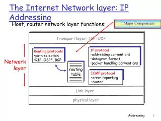
The Interior Gateway Routing Protocol • The Internet is made up of a large number of autonomous systems(AS) • Two-level routing: • interior gateway protocol – a routing algorithm within an AS. • exterior gateway protocol – a routing algorithm between Ases.
OSPF – Open Shortest Path First • OSPF supports three kinds of connections and networks: • Point-to-pint lines between exactly two routers. • Multiaccess networks with broadcasting (e.g., most LANs.) • Multiaccess networks without broadcasting (e.g., most packet-switched WANs). • OSPF represents the actual network as a graph like this and then compute the shortest path from every router to every other router.
OSPF – The Interior Gateway Routing Protocol (a) An autonomous system. (b) A graph representation of (a).