Download
1 / 31
340 likes | 710 Vues
SLAC KLYSTRON LECTURES. Lecture 9 March 31, 2004 Other Microwave Amplifiers TWT, CFA, Gyro-amplifier, SSA Robert Phillips, rphil@slac.stanford.edu Glenn Scheitrum, glenn@slac.stanford.edu Stanford Linear Accelerator Center. Suggested Resources:

E N D
SLAC KLYSTRON LECTURES Lecture 9 March 31, 2004 Other Microwave Amplifiers TWT, CFA, Gyro-amplifier, SSA Robert Phillips, rphil@slac.stanford.edu Glenn Scheitrum, glenn@slac.stanford.edu Stanford Linear Accelerator Center
Suggested Resources: Movie viewer: Quicktime, RealPlayer, etc. References: Traveling Wave Tubes, J. Pierce, Principles of Traveling Wave Tubes, A.S. Gilmour, 1994 The electron cyclotron maser, K.R. Chu, Review of Modern Physics, 2004 Microwave Power Engineering, Vol. 1, E. Okress editor, Academic Press, 1968 Microwave Magnetrons, Collins, MIT Radiation Laboratory Series, V6, 1947
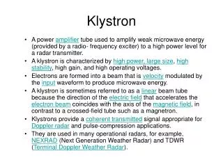
TWT – THE OTHER LINEAR BEAM TUBE • Brief History – Development and application • How TWT’s differ from klystrons • Why TWT’s, not klystrons • Characteristics of two basic types: • Transmission line circuit • Waveguide circuit • Operating principles and characteristics summarized
Pioneers • 1933 Haeff TW deflection devices • 1940 Lundenblad TW amplifier • 1943 Kompfner Early amplifiers • 1946 Pierce Early work at Bell Labs. • Published complete theory. • “Traveling Wave Tubes,” 1950.
TWT vs. Klystron • Similarities: • Beam formation, focusing and collection are the same • Input and output rf coupling are similar • TWT uses a traveling wave version of the discreet cavity interaction of the klystron • Large overlays in beam voltage, current and rf power output • Differences: • Bandwidth • Klystron ≈ 1% • Waveguide TWT ≈ 10% • Transmission Line (Helix) TWT ≈ 1 - 3 octaves • Form factor more amenable to low-cost, light-weight PPM focusing • Market Impact of Difference • A single ECM TWT tube type produced by Varian for ECM produced in greater numbers than all of the klystron amplifier tubes ever built.
Basic Helix TWT If this were a coax line in TEM mode (not coiled), vp/c = 1, independent of frequency, with unlimited bandwidth and no axial E. By coiling the conductor, axial velocity is reduced by the amount of the increase in path length, a substantial Ez is created, and vz remains largely independent of frequency. Gain is obtained by synchronizing the beam velocity with the axial wave velocity (from Principles of Traveling Wave Tubes, A. S. Gilmour)
ω-β diagram showing -1 space harmonic (from Principles of Traveling Wave Tubes by A. S. Gilmour)
9” Photograph of ring-loop circuits, L-band through Ku-band
ω-β diagram for connected ring circuit showing -1 space harmonic suppressed
ω-β diagram for periodically-loaded waveguide (from A. S. Gilmour)
Coupled-cavity circuit – a practical embodiment of a folded waveguide
Cloverleaf fundamental forward wave circuit produced 5 MW peak power at 10% BW
Gyro-amplifiers • Gyro-TWT – medium power, high gain, moderate bandwidth, 15%-30% efficiency • Gyro-klystron – high power, high gain, low bandwidth, 20%-40% efficiency
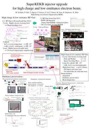
Gyro-amplifiers – electron cyclotron maser interaction devices Basic interaction physics: In a magnetic field, electrons orbit flux lines at the cyclotron frequency where e is the electron mass, m0 is the electron mass and B0 is the magnetic field in Tesla If an RF electric field is applied in the orbit plane, the momentum of the orbiting electrons will be modulated. Negative mass effect: Electrons which gain energy have increased mass, larger orbit radius, and reduced angular velocity.
Available beam power is proportional to beam area. Compare beam area of helix, coupled cavity (similar to klystron), and cutoff overmoded waveguide of gyro-amplifier. Tunnel size in TWTs and klystrons limited by ga, gyro-amplifiers use overmoded waveguide sections. For a gyroklystron, rb is limited by need to have drift tubes cut off to operating mode
Gyrodevices interact with the transverse momentum of the beam Parameter a = v / v║ is the ratio of transverse to parallel velocity Normal range of a is 1 – 2 making the rotational energy 50% to 80% of total beam energy At an a of 1, a total efficiency of 30% implies a rotational efficiency of 60% It is important to minimize energy spread in the beam as the efficiency drops dramatically with increased axial velocity spread. This is especially important in gyro-amplifiers where axial velocity spread smears the bunch longitudinally as it drifts between cavities.
CPI-Northrop-NRL 94 GHz Gyroklystron 100 kW peak power 10 kW average power 0.7% bandwidth
Crossed field amplifiers • High peak and average power, high efficiency, 10% bandwidth devices • Low gain ~10 dB, needs multi-device amplifier chain • Noise due to cycloidal electron trajectories • Current produced by secondary emission, no heater required
Equations of motion for an electron in crossed electrostatic and magnetostatic fields Non relativistic Lorentz force equation F = ma = q ( E + v x B ) For planar magnetron this separates into three orthogonal components Ez By z Assume constant Ez and By Ex=Ey=Bx=Bz=0 x Integrating d2x/dt2, defining initial conditions and substituting into d2z/dt2 yields Solving for z (and x) gives
Block diagram of CFA amplifier chain at 11 GHz for multi-megawatt system Solid state Driver 10 W TWT or klystron Intermediate amp 30 dB 10 kW CFA +10 dB 100 kW CFA +10 dB 1 MW CFA +10 dB 10 MW
Solid State Amplifiers (SSAs) • Broad bandwidth, low power, moderate gain, low noise, low efficiency devices • Small size, low cost manufacturing process • Ideal for use as drivers for high power sources • Two basic transistor types BJTs and FETs • Both are used at 3 GHz for power amplifiers but FETs dominate at higher frequencies • Both are limited in frequency by transit time effects that are similar to those encountered by vacuum triodes • New materials GaAs and GaN produce higher mobility carriers and higher breakdown voltage to extend the performance envelop of solid state amplifiers
Summary The discussion has covered solid state amplifiers, traveling wave tubes, crossed field amplifiers, and gyro-amplifiers. Obviously solid state amplifiers and traveling wave tubes do not produce the high peak power required for accelerator sources. They function well as drivers and as low power, wide bandwidth sources. CFA’s and gyroklystrons can produce the required power but each has significant handicaps in comparison to a high power klystron. The CFA can produce efficiencies in excess of 70% but has very low gain and requires a multi device amplifier chain to drive the final output CFA. The gyroklystron has a problem with device efficiency, increasing a to minimize the energy in axial velocity causes increased axial velocity spread in the beam. Gyro-amplifiers use overmoded RF circuits and therefore have a heat transfer advantage as the frequency increases.