Download
1 / 21
230 likes | 400 Vues
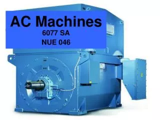
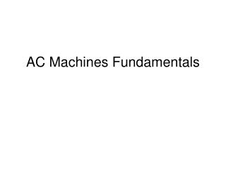
Three-Phase AC machines. Resource 7. Three-Phase Synchronous Machines. Three-Phase Synchronous Machines. Three-Phase AC Machines Resource 7. Aim. To understand the construction and operation of a three-phase synchronous machine. Three-Phase AC Machines Resource 7.

E N D
Three-Phase AC machines Resource 7 Three-Phase Synchronous Machines
Three-Phase Synchronous Machines Three-Phase AC Machines Resource 7 Aim • To understand the construction and operation of a three-phase synchronous machine
Three-Phase AC Machines Resource 7 Three-Phase Synchronous Machines Objectives • To be able to describe the construction of the stator • To be able to describe the construction of a salient pole rotor • To be able to describe the construction of a cylindrical rotor • To be able to describe the operation of a synchronous machine as a generator • To be able to calculate synchronous speed and terminals voltage • To be able to describe the operation of a synchronous machine as a motor
Stator Construction • Stator is identical to the induction motor • Laminated low silicon steel rings joined together • Slots insulated with Mylar • Example of 36 slot stator with 3 coil conductors per slot, 12 slots per phase
Stator Construction Stator frame • Stator is identical to the induction motor • Laminated low silicon steel rings joined together Stator slots with insulator • Slots insulated with Mylar • Example of 36 slot stator with 3 coil conductors per slot, 12 slots per phase • Slot insulator inserted by hand
Stator Construction Stator frame • Stator is identical to the induction motor • Laminated low silicon steel rings joined together Stator slots with insulator • Slots insulated with Mylar Coil • Example of 36 slot stator with 3 coil conductors per slot, 12 slots per phase • Slot insulator inserted by hand • Coils inserted by hand
Stator Construction • Coils can be placed in single or double layers Stator slot
Stator Construction Single layer Coil 1 coil arm per slot Stator Slots
Stator Construction Stator Slots Double layer Coil 2 coil arms in each slot
Stator Construction Stators can be very large
Rotor Construction Two types of rotor • Salient Pole • Cylindrical
Rotor Construction Salient Pole Difference between pole face curvature and stator creates non-linear variation in flux across pole face Non-linear variation in flux across pole face produces sinusoidal change in the induced EMF
Rotor Construction Cylindrical Difference in coil spacing creates non-linear variation in flux around the rotor surface Non-linear variation in flux around rotor surface produces sinusoidal change in the induced EMF
Rotor Construction Cylindrical Difference in coil spacing creates non-linear variation in flux around the rotor surface Non-linear variation in flux around rotor surface produces sinusoidal change in the induced EMF
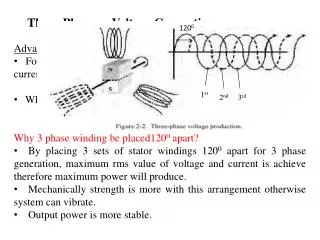
A’ B C C’ B’ A A’ B C C’ B’ A N S Operation as a Synchronous Generator Two pole cylindrical rotor example • Field produced on rotor by dc current through slip rings • Rotor field is turned at 3000rpm by a prime mover • EMFs induced in stator coils with frequency of 50Hz • Magnetic Flux distributed around rotor produces sinusoidal variation in induced EMF • Phase coils separated by 120o causes delay between phase EMFs
Operation as a Synchronous Generator Two pole cylindrical rotor example Period = 20ms • Field produced on rotor by dc current through slip rings C A B • Rotor field is turned at 3000rpm by a prime mover • EMFs induced in stator coils with frequency of 50Hz • Magnetic Flux distributed around rotor produces sinusoidal variation in induced EMF • Phase coils separated by 120o causes delay between phase EMFs • Delay between phases = 20/3 = 6.667ms 6.667ms
Calculations Synchronous speed fS = supply frequency required RPM p = pole pairs Induced EMF Volts per phase Φ = flux per pole set by rotor current z = conductor in series per phase
Operation as a Synchronous Generator Generated EMF relationship Open circuit stator EMF The open circuit EMF generated depends upon saturation • Rotor speed • Rotor current Relationship between open circuit stator EMF and rotor current is a straight line until the steel begins to saturate when it becomes non-linear. linear Rotor current
NS A’ NR B C’ B’ A N S Operation as a Synchronous Motor Two pole cylindrical rotor example • Stator field rotates at 3000rpm from 50Hz supply • Rotor field must be locked on to stator field speed • Motor runs a synchronous speed whatever the mechanical load provided rotor field is strong enough NR = NS • This is impossible within an induction motor as there wound be no induced currents to cause rotation • This motor runs at synchronous speed hence the name – SYNCHRONOUS MOTOR
Operation as a Synchronous Motor Two pole cylindrical rotor example • Stator field rotates at 3000rpm from 50Hz supply • Rotor field must be locked on to stator field speed • Motor runs a synchronous speed whatever the mechanical load provided rotor field is strong enough Rotor Speed (NR) NR = NS NS • This is impossible within an induction motor as there wound be no induced currents to cause rotation • This motor runs at synchronous speed hence the name – SYNCHRONOUS MOTOR Load Torque
Operation as a Synchronous Motor The V-curve The rotor current can be adjusted to vary the power factor of the stator Unity power factor is achieved when stator current is at its minimum This machine can be used to correct power factor of induction motors when connected in parallel