Download
1 / 26
260 likes | 390 Vues
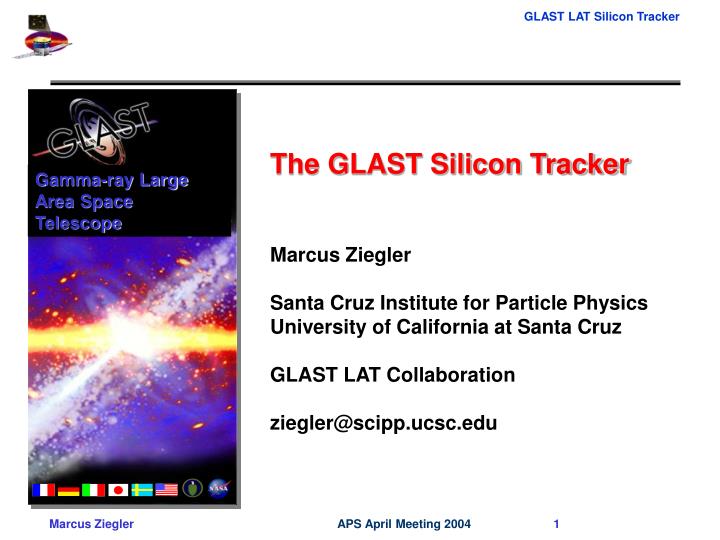
Gamma-ray Large Area Space Telescope. The GLAST Silicon Tracker Marcus Ziegler Santa Cruz Institute for Particle Physics University of California at Santa Cruz GLAST LAT Collaboration ziegler@scipp.ucsc.edu. Gamma-ray Large Area Space Telescope. GLAST Mission

E N D
Gamma-ray Large Area Space Telescope The GLAST Silicon Tracker Marcus Ziegler Santa Cruz Institute for Particle Physics University of California at Santa Cruz GLAST LAT Collaboration ziegler@scipp.ucsc.edu
Gamma-ray Large Area Space Telescope • GLAST Mission • High-energy gamma-ray observatory with 2 instruments: • Large Area Telescope (LAT) • Gamma-ray Burst Monitor (GBM) • Launch vehicle: Delta-2 class • Orbit: 550 km, 28.5o inclination • Lifetime: 5 years (minimum) • GLAST Gamma-Ray Observatory: • LAT ~20 MeV and up • GBM 20 keV to 20 MeV • Spacecraft bus LAT Routine Data GBM
Outline • Introduction • Collaboration wide effort Italy/US/Japan • Tracker construction – fine • SSD - fine • MCM – fine • Electronics Mounting -fine • Tray ? • READOUT scheme –fine • Mention zero suppression, binary readout and redunduncy • EM Calibration results • Trigger rate per tray • Charge injection for TOT linearity • Efficiency vs DAC • Efficiency vs TACK delay
Heavy metal foils (e.g. tungsten) convert high-energy gamma rays into electron-positron pairs. Detectors interleaved with the converter foils track the charged particles. The gamma-ray direction is reconstructed from the tracks. A calorimeter absorbs the electromagnetic shower and records the gamma-ray energy. Veto counters reject background from the predominant charged cosmic rays (electrons, protons and heavy ions). Pair-Conversion Telescope Multiple-scattering limits angular resolution
ACD Veto Counters Segmented scintillator tiles Grid (& Thermal Radiators) e– e+ GLAST LAT Overview Si Tracker 8.8105 channels 185 Watts CsI Calorimeter 8.4 radiation lengths 8 × 12 bars 3000 kg, 650 W (allocation) 1.8 m 1.8 m 1.0 m Effective area ~1 m2
Tracker Construction- Overview Carbon composite side panels Tested SSDs procured from Hamamatsu Photonics 4 SSDs bonded in series. 19 “trays” stack to form one of 16 Tracker modules. 10,368 2592 Electronics and SSDs assembled on composite panels. “Tray” 342 342 18 648 Kapton readout cables. Electronics mount on the tray edges. Chip-on-board readout electronics modules. Composite panels, with tungsten foils bonded to the bottom face.
~80 m2 of PIN diodes, with P implants segmented into narrow strips. Reliable, well-developed technology from particle-physics applications. A/C coupling and strip bias circuitry built in. >2000 detectors already procured from Hamamatsu Photonics. Very high quality: Leakage current < 2.5 nA/cm2 Bad channels < 1/10,000 Full depletion < 100 V. Silicon Strip Detector 8.95 cm square Hamamatsu-Photonics SSD before cutting from the 6-inch wafer. The thickness is 400 microns, and the strip pitch is 228 microns.
Multi Chip Module (MCM) The 24 readout chips (GTFE) of each MCMC are controlled by 2 controller chips (GTRC) at the edges Shown prior to wire-bond encapsulation and conformal coating. One of the challenges of this design in the Pitch-adapter flex circuit used to route the signals from the detectors to the front-end electronics
Hybrid Boards (MCM) Silicon detector • Binary readout • Redundancy scheme • Zero suppression GTFE GTRC Corner post boss for attachment connector
Machined corner radius with bonded flex circuit. Detector Composite Panel Readout IC High thermal conductivity transfer adhesive PWB attached by screws Electronics Packaging • Dead area within the tracking volume must be minimized. • Hence the 16 modules must be closely packed. • This is achieved by attaching the electronics to the tray sides. • Flex circuits with 1552 fine traces are bonded to a radius on the PWB to interconnect the detectors and electronics. Detector signals, 100 V bias, and ground reference are brought around the 90° corner by a Kapton circuit bonded to the PWB.
Electronics Mounting Silicon ladder Readout chip kapton Attachment fixture Tray Tray main issues Hybrid board • gluing • alignment • assembly time After bending Before bending kapton
Readout Electronics • Based on 2 ASICs developed exclusively for this project: • 64-channel amplifier-discriminator chip (GTFE); 24 per module. • Readout controller chip (GTRC); 2 per module. • Two redundant readout and control paths for each GTFE chip (“left” or “right”) makes the system nearly immune to single-point failures. • Programmable channel masks and threshold DACs. • Internal, programmable charge-injection system. • Trigger implemented from OR of all channels/layer.
Readout Sequence Command Clock trigger GTFE – front end readout chip GTFC – readout controller chip TEM – tower electronics module Fast OR & Data . . . TEM GTFE GTFE Command GTFC Clock Trigger Fast OR GTFE GTFCTEM Trigger TEMGTFCGTFE Read Event GTFE GTFC Data GTFE GTFC Token GTFCTEM Fast OR Data Token
Bias Circuits SSDs Panel Tungsten MCM Mechanical Structure • Carbon-fiber composite used for radiation transparency, stiffness, thermal stability, and thermal conductivity. • Honeycomb panels made from machined carbon-carbon closeouts, graphite/cyanate-ester face sheets, and aluminum cores. • High-performance graphite/cyanate-ester sidewalls carry the electronics heat to the base of the module. • Titanium flexure mounts allow differential thermal expansion between the aluminum base grid and the carbon-fiber tracker. Bottom Tray Flexure Mounts Thermal Gasket
Performance • The LAT silicon tracker performance has been studied in several ways: • Detailed Monte Carlo simulation. • Beam tests and cosmic-ray studies with prototype detector assemblies. • A high-altitude balloon flight. • Data from the prototypes have been used to tune and validate the simulation model.
1997 Beam Test—Verify Simulation Model Small-aperture first prototype Operated in a tagged beam at Stanford Data Monte Carlo Published in NIM A446 (2000), 444.
Beam Test of a Complete Module • Full-scale Tracker module with 51,200 readout channels operated in positron, photon, and hadron beams at Stanford Linear Accelerator Center. • The Tracker power, noise, and efficiency requirements were met: • 99% efficiency with <105 noise occupancy. • Only 200 W of power consumed per channel. NIM 457, 466, & 474 Operating Point Hit efficiency versus threshold for 5 GeV positrons.
First full-scale carbon-composite tracked module mechanical structure. Thermal cycling, vacuum testing, and random vibration testing have been carried out at the tray and tower-module levels. Results were satisfactory except that the joint between the corner flexures and the bottom tray failed at the highest vibration levels—work is in progress to reinforce the joint. Carbon-Composite Mechanical Prototype Bottom tray panel, electronics side Bottom tray panel, orthogonal side Full module instrumented for thrust-axis vibration
January 2002: NASA PDR & DOE Baseline Review. Present: complete the Engineering-Model tracker module: Complete mechanical-thermal module with dummy silicon detectors. 4 fully instrumented and functional trays. Winter 2003: Critical Design Review follows Engineering-Model testing. First 2 of 18 tracker modules completed and ready for qualification testing by the end of 2003. Final tracker modules completed by September 2004. LAT Integration and Test until mid 2005. Launch in 3rd quarter of 2006. LAT Tracker Status and Schedule
Conclusions • Solid-state detector technology and modern electronics enable us to improve on the previous generation gamma-ray telescope by well more than an order of magnitude in sensitivity. • The LAT tracker design uses well-established detector technology but has solved a number of engineering problems related to putting a 900,000 channel silicon-strip system in orbit: • Highly reliable SSD design for mass production • Very low power fault-tolerant electronics readout • Rigid, low-mass structure with passive cooling • Compact electronics packaging with minimal dead area • We have validated the design concepts with several prototype cycles and are now approaching the manufacturing stage. • We’re looking forward to a 2006 launch and a decade of exciting GLAST science!
SSD Testing or Ladder testing • Get a plot with some stats • Say how great the yield is and how important it is to have alarge yield for space applications (can’t fix it up tehre). Has to be be good