Download
1 / 87
870 likes | 888 Vues
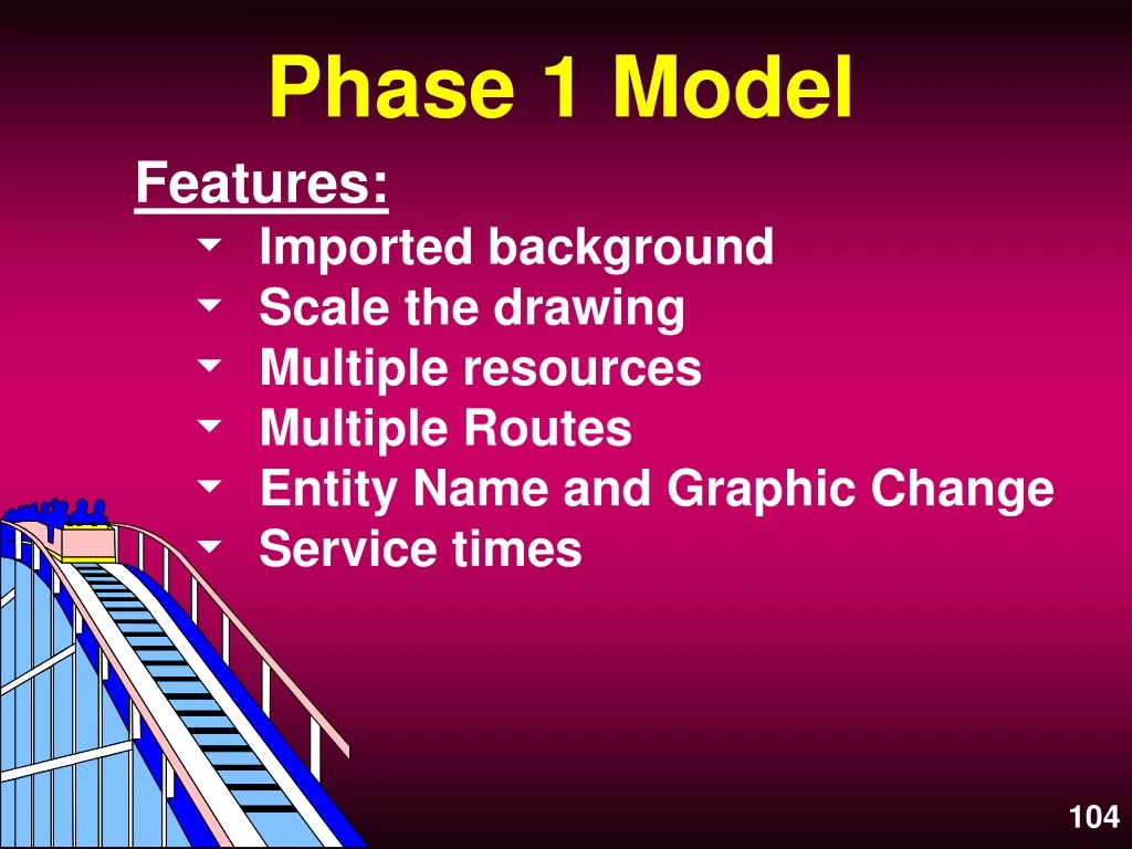
Phase 1 Model. Features: Imported background Scale the drawing Multiple resources Multiple Routes Entity Name and Graphic Change Service times . Multiple Routes. One Route with multiple destinations. One route, multiple destinations. Phase 2 Model. Features:

E N D
Phase 1 Model • Features: • Imported background • Scale the drawing • Multiple resources • Multiple Routes • Entity Name and Graphic Change • Service times
Multiple Routes • One Route with multiple destinations.
Phase 2 Model • Features: • Attributes • Resource & Location Downtimes • Mathematical & User Distributions • New Operation Statements • Logs
Attributes • Assigned to Locations or Entities. • Not global. • Assigned to all entities or locations. Initial value always zero. • May be Real or Integer • Used for identifying entity differences, conditional routing, LOG reporting, ...
Location Downtimes • Four Types; Clock, Entry, Usage, Setup • Usage • Records the total cumulative time the • location is in operation • Upon reaching the defined cumulative • time, location goes down • Downtime logic defines length of • downtime and any action necessary
Resource Downtimes • Clock or Usage • Logic Field is the length of the downtime • May be Scheduled or Unscheduled • Preemptable
User Distributions 1. User defined Distribution tables may be created under the Build - More Elementsmenu. 2. Used to define user created distributions. 3. Sampled from by calling TABLE_NAME() in a logic field. This will assign the sampled value to an attribute or variable. aType_of_Call = dCall_Dist()
Click on “Table” to open definition window
Operation Statements • Assignment ( i.e. = ) Not really a statement, just setting one item equal to another Syntax: vProcess_Time = N(3.2,.47) • DISPLAY Pauses the simulation and displays a user created message Syntax: DISPLAY <“string text message”>
Operation Statements • CLOCK() Returns the value of the system simulation clock. Used for a test or to store the value. Syntax: aStart_Time = CLOCK() • ROUTE # Defines which of the numbered routings you are referring to in a logic statement Syntax: If aPart_Type=1 then ROUTE 6
If-Then-Else, Begin-End, Route IFAttr1 <= 10THEN BEGIN WAIT N(25,5, 3) Attr1=11 ROUTE 1 END ELSE ROUTE 2 BEGIN may be symbolized with a Left Bracket --- { END may be symbolized with a Right Bracket --- }
Operation Statements • LOG Subtracts the time stored in an attribute from the current system clock time and stores the value for later reporting Syntax: LOG “Process Report”, aStart
Phase 3 Model • Features: • Variables • Routing Rules • New Operation Statements • Special Location Icons • New Resource • New Path Network
Global Variables • Carry a numeric value • Used for decision making or recording values • May be INCremented, DECremented or assigned values • As a global variable it may only have one value at a time • Initial value is changeable • May be displayed on the screen
Variable edit table Variables displayed on the layout
Routing Rules • UNTIL FULL Fills the first destination listed until it is capacitated, then the next one, etc. Syntax: FULL <quantity expression> • PROBABILITY Randomly selects a destination listed in a block of routings based on a probability Syntax: .43 .57
Operation Statements • INC Increments or adds a value to a variable, attribute or array cell Syntax: INC vCounter, <by how much> • DEC Decrements or subtracts a value from a variable, attribute or array cell Syntax: DEC vCounter, <by how much>
Operation Statements • GROUP Consolidates and accumulates a specified number of entities into a single entity that has a new name. The new entity is named as the output entity. Syntax: GROUP <numeric expression>
Operation Statements • UNGROUP Separates entities that were GROUPed using the GROUP statement. After UNGROUPing, you must have a process defined at the ungroup location for all entities that could be within the grouped entity. There is NO routing entry AT ALL after an UNGROUP statement. Syntax: UNGROUP
Operation Statements • JOIN Both a Routing Rule AND an Operation Statement. As a Routing Rule: holds the entity at current location until another entity at a different location calls for it with a JOIN Operation Statement. As an Operation Statement: causes the waiting entity to be released. Syntax: JOIN <how many><entity name>
Phase 4 Model • Features: • Multiple Numbered Routes • Shift Scheduling • Static Resource • New Operation Statements
Multiple Routes • Multiple numbered Routes with operation logic to determine which route to execute.
Multiple numbered routes, logic determines which to execute
Click on “Start New Block” to get a new number in the routing line
Shift Scheduling • Define shifts from the BUILD - SHIFTS - DEFINE menu. • Shift and Break periods may be defined in 1 minute increments. • Save the created shift with a file name. • Assign Resources and Locations to the shift from the BUILD - SHIFTS - ASSIGN menu.
Shift Scheduling • Different priorities for starting a break or an off shift may be defined. Different priorities for while on break or on shift may also be defined. • Logic may be applied to break and offshift periods as well as pre-break and pre-offshift periods.
Choose from Define or Assign
Note ability to modify shift
Priorities for ending shift, off shift, starting break and break. Several locations and resources may be assigned to the same shift. Resources within a single group (e.g. 5 repairman) may be assigned to different shifts. Logic for pre-off shift, off shift, pre-break and break is entered here.
Static Resources • Used for immobile resources • Do not require assignment to a path network • Place the graphic directly on the layout where you want the resource • Changes color to show status
Static Resources: Select the graphic, click on the add button and click on the layout
Routing Path Movement • Entities may be moved on Routing Paths (process arrows) • They may only move for a time expression - use the MOVE FOR statement in Move Logic • Routing paths may be bent by adding joints with a right click