Download
1 / 8
90 likes | 199 Vues
1.5 GHz Sub-Harmonic Bunchers. past – present – perhaps future. L. Timeo on behalf of S. Rey and H. Shaker. Feb 10, 2012. 1. some consideration (1).

E N D
1.5 GHz Sub-Harmonic Bunchers past – present – perhaps future L. Timeoon behalf of S. Rey and H. Shaker Feb 10, 2012 1
some consideration (1) • from “Proceedings of EPAC 2006, Edinburgh, Scotland” - MOPLS101 - (http://accelconf.web.cern.ch/accelconf/e06/PAPERS/MOPLS101.PDF) we know that: “Since the beam loading is different in each of the three SHBs, the structures are individually detuned [5]. The common parameters for the SHBs are listed in Table 1.” Feb 10, 2012 L. TIMEO 2
some consideration (2) • from “Proceedings of EPAC 2006, Edinburgh, Scotland” - MOPLS102 - (http://accelconf.web.cern.ch/accelconf/e06/PAPERS/MOPLS102.PDF) we know this is the layout: Feb 10, 2012 L. TIMEO 3
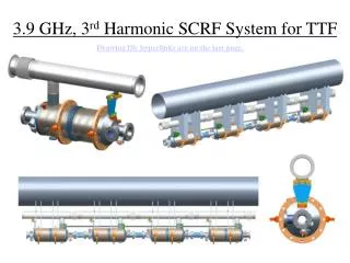
some consideration (3) • from [5] “CTF3 Note 071: Parameter list of the CTF3 Linac and the CT line” (http://clic-study.web.cern.ch/CLIC-Study/CTF3/Notes/CTF3_071.pdf) and following the inspection in the tunnel we know that: • SHBs are travelling wave cavities (cables are used as loads); • PB is a standing wave cavity (fed by wall side); • Buncher is a travelling wave structure; • ACS03 is a travelling wave structure, as well. Feb 10, 2012 L. TIMEO 4
time-domain reflectometry SHB03 SHB01 Courtesy of S.Rey Courtesy of S.Rey SHB02 Courtesy of S.Rey Feb 10, 2012 L. TIMEO 5
Δ13=7.75MHz Δ23=1.38MHz Δ12=6.38MHz Δ13=-5.25MHz Δ23=1.38MHz Δ12=-6.63MHz Δ13=-1.63MHz Δ23=0.88MHz Δ12=-2.50MHz Feb 10, 2012 L. TIMEO 6
overview of all S parameters SHB01 SHB03 From these 3 plots we can conclude the transmission seems to be good enough, but there is a strange behavior in S11 and S22 of SHB02. SHB02 Feb 10, 2012
conclusion • Hamed said that theoretically “the resonant frequencies of SHB1 and SHB2 should be about 10.1 and 3.0 MHz more than SHB3, respectively”, but this does not really correspond to the measurement. • we can identify also different behaviors after 1.52GHz, in particular for SHB02 where we can notice some difference especially in its S11, but no final conclusion can be achieved. • we shall repeat the measurement once the water station will run again and compare new results with theoretical ones. Feb 10, 2012 L. TIMEO 8