Download
1 / 38
380 likes | 493 Vues
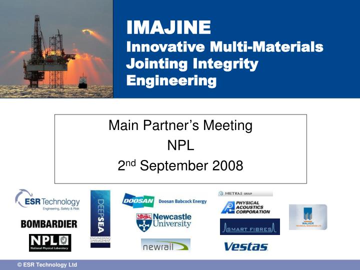
Main Partner’s Meeting NPL 2 nd September 2008. IMAJINE Innovative Multi-Materials Jointing Integrity Engineering. Agenda. Welcome General IMAJINE project overview Work Tasks – Summary of activities EPSRC/University activities Case Studies Overview

E N D
Main Partner’s Meeting NPL 2nd September 2008 IMAJINE Innovative Multi-Materials Jointing Integrity Engineering
Agenda • Welcome • General IMAJINE project overview • Work Tasks – Summary of activities • EPSRC/University activities • Case Studies • Overview • Individual Case Study plans and details discussion • Concluding remarks • AoB Meeting close (15.00)
Partners Engineering Contractors: ESR (lead), NPL, Doosan Babcock and Deepsea University: Newcastle Industrial partners: Vestas, Walkers, Bombardier, Physical Acoustics, Smartfibres
Project overview • TSB Technology Programme : Project: IMAJINE aims to develop structural health monitoring and integrity assessment procedures along with best practice guidance for joint (adhesive and mechanical) durability under the application of static and fatigue loading and environmental exposure. Start date 1st April 2008 – Duration 36 months Value of project is 1.84 million pounds (50/50 cash, in-kind) IMAJINE consists of; • 7 Work Tasks • 4 Case Studies • 1 University project
Purpose of today’s meeting Discuss Work Tasks and Case Studies in more detail, which industrial partners are involved and their contribution Present content, detail and deliverables for each of the 6 work tasks – take on board comments Ensure correct linkage between the University project and relevant work tasks Arrangements for Dissemination of information
Relationship between the various activities Task 1 What type of joints and materials • CASE STUDIES • 1. Wind turbine blade • . Rail cab structure • . Structural strengthening 4. Piping repair Task 4 Integration of monitoring techniques Task 2 Development of assessment techniques Task 5 How to interpret data Task 6 How to exploit monitoring technology Task 3 Assessment of NDE, monitoring techniques EPSRC project – development of monitoring systems Task 0 Project management
Previous activities Past DTI/TSB projects; MMS13 – Assessment and criticality of defects and damage in Composite Material Systems – will be used as basis for Task 6 MMS15 – Interactive knowledge base on NDE of Composites – will be used as the basis for Task 3 ACLAIM – Integrity management framework for composite components – short term Emphasis of this project is on long term loading and environmental effects
Non-technical issues Package of information: Offer letter from the TSB Framework for collaboration Declaration by participating company Reimbursement – TSB will be invoiced quarterly after ESR receives expenditure submissions from partners – explanation in offer letter. Q1 collection in progress ESR will pay invoices from Partners after payment from TSB received
Other industry invitees In the previous DTI/TSB project one of the key successful was the contribution of industry members Should we invite other industry representatives to attend progress meetings to give their opinions and comments on work to date If so, suggestions on who to invite? Also, commercial issues, e.g. non-disclosure agreement.
Task descriptions Task 0 – Project management (ESR) Task 1 – What types of joints and materials? (NPL) Task 2 – Development of durability assessment techniques (NPL) Task 3 – Assessment of NDE and monitoring techniques (NewRail) Task 4 – Development and integration of condition monitoring techniques (DB/Deepsea) Task 5 – How to interpret monitoring data (ESR/Deepsea) Task 6 – How to exploit condition monitoring technology (DB/NPL)
Task 0 – Project management Involved with organising meetings, industry participation, quarterly reporting, invoicing. Other activities: Liasing with TSB and TSB monitor (Ross Hannan) Develop web site www.imajine.co.uk Organise progress meetings (4 per year) Ensuring overall project is progressing as planned
Task 1 – What types of joints and materials This task will define the specific types of joints and configurations to be considered in the 4 Case Studies and identify the critical integrity performance indicators . CS1 – Wind turbine blade – secondary bonded and resin infused joints between various structural components fabricated from glass fibre-reinforced plastic (GFRP), wood and carbon fibre reinforced plastic (CFRP). CS2 – Train body components - joints between the cab (GFRP/foam sandwich) and the main vehicle body-shell (steel or aluminium). CS3 – Structural strengthening - adhesively bonded joint consisting of CFRP strengthening beams to metallic substrates CS4 – Pipe repair - GRP over-wrap repairs on steel and GFRP pipes
Task 2 – development of durability assessment techniques This Task will develop test protocols for assessing the durability of the case study joints under constant and variable amplitude (spectral) fatigue loading. For each case study, long-term loading tests will be undertaken using the developed protocols and measurements will be made of the key structural performance indicators (e.g. mode I fracture toughness of adhesive joints) identified in Task 1 and required for Task 5. It is intended that these test protocols for joint performance indicators will be standardised.
Task 3 – Assessment of NDE/monitoring techniques • This Task will assess the suitability of NDE and novel condition monitoring techniques for the detection of damage onset and growth and real-time monitoring of joint performance indicators based on the input from Task 1 • Initial Assessment – trials will be performed using candidate NDE and monitoring techniques to assess which techniques offer the most potential for application • Screening – the most promising techniques identified in stage (i) will be used to monitor joint performance throughout the durability tests undertaken in Task 2. • NDE techniques to be considered will include, AE, AU, dielectrics, microwaves. • Novel monitoring techniques to be considered include embedded nano-particles, fibre optics, ‘smart’ mechanical fasteners and conductive adhesives.
Task 4 – Integration of condition monitoring techniques This task will look at the development requirements of those NDE/monitoring techniques successfully screened in Task 3 to formulate strategies for their practical implementation How they can be incorporated into joints for use in-service.
Task 5 – How to interpret inspection/monitoring data? This Task will involve the analysis and interpretation of data (from techniques and their sensitivities identified in Task 3) in terms of the critical performance parameters (from defined in Task 1) obtained from NDE and monitoring techniques It is expected that the primary parameters will be fracture based (continuing the development of the assessment models developed within the ACLAIM project) The Case Studies will be used to validate the theoretical models via comparison of actual joint performance data to the predicted behaviour.
Task 6 – How to exploit condition monitoring data This task will define industrially relevant techniques for inspection and condition monitoring of jointed multi-material structures, i.e. addressing the practical issues of implementing condition monitoring systems. Key to this is to ensure that recommended techniques can be deployed at minimal cost and in a variety of industrial environments. Recommendations as to how condition monitoring data can be used to optimise joint design, safety and reliability will be made. The task will also summarise the conclusions of the project by production of a best practice guide for integrity assessment of multi-material joints.
University Project - Aims To investigate the application of remote sensing technologies such as acoustic emission (AE), acousto-ultrasonics, dielectrics and microwaves to joints in lightweight multi-material structures (with the exception of weld cracking). The aim is to overcome current limitations and demonstrate their viability. To investigate the application of embedded sensor technologies such as fibre optics and demonstrate their viability. To apply recent developments in pattern recognition analysis and neural networks for the improved handling of complex monitoring, inspection technique signals to allow for improved characterisation of damage development.
Case studies 4 Case Studies Still to be finalised, in terms of plans and contents Case study 1 – Wind turbine blade (NPL/DB) Case study 2 – Rail cab (NewRail/ESR) Case study 3 – Structural strengthening (ESR/Deepsea) Case study 4 – Piping repair (DB/Deepsea/ESR) Purpose of the Case Studies is to provide the verification of the health monitoring and assessment procedures developed in the Tasks. Emphasis on long-term and durability
Case study 1 – Wind turbine blade Failure mode of concern – Interfacial delamination • Need to define • Selection of relevant geometry for consideration • Determination of the relevant loading regimes and environment • Test specimen provision • Testing and inspection plans • Which partner will lead? – NPL • Which partner will support?
Case study 1 – Wind turbine blade Case Study activities to include; • Determination of critical energy release rates for the specific geometry, loading conditions and environment • Measurement of the failure loads for the specific test geometries • Prediction of failure loads • Trials of recommended monitoring/inspection techniques • Assessment of the significance of defects as a function of applied loads and environment • Development of assessment procedure
Case study 2 – Rail cab • Need to define • Selection of relevant geometry for consideration, i.e. bolted, flanged, bonded • Determination of the relevant loading regimes and environment • Test specimen provision • Testing and inspection plans • Relevant failure mode(s) • Which partner will lead? – NewRail • Which partner will support?
Case study 2 – Rail cab Case Study activities to include; • Determination of critical performance indicators for the specific loading conditions, • Measurement of the failure loads for the specific test geometries and environments • Prediction of failure loads • Trials of recommended monitoring/inspection techniques • Assessment of the significance of defects as a function of applied loads • Development of assessment procedure
Case Study 3 – Structural strengthening • Need to define • Selection of relevant geometry for consideration (not necessarily bridges!) • Determination of the relevant loading regimes and environment • Test specimen provision • Testing and inspection plans • Which partner will lead? – ESR • Which partner will support? Failure mode of concern – Interfacial delamination
Case study 3 – Structural strengthening Case Study activities to include; • Determination of critical performance indicators for the specific loading conditions, • Measurement of the failure loads for the specific test geometries and environments • Prediction of failure loads • Trials of recommended monitoring/inspection techniques • Assessment of the significance of defects as a function of applied loads • Development of assessment procedure
Case study 4 – Piping repair Failure mode of concern – Interfacial delamination • Need to define • Selection of relevant geometries (including substrates, surface preparation) for consideration • Determination of the relevant loading regimes (static, cyclic) and environment • Test specimen provision • Testing and inspection plans • Which partner will lead? – NPL • Which partner will support?
Case study 4 – Piping repair Case Study activities to include; • Determination of critical energy release rates for the specific geometry and loading conditions, • Measurement of the failure loads under the defined loading conditions (cyclic, static) for the specific test geometries and environment • Prediction of failure loads • Trials of recommended monitoring/inspection techniques • Assessment of the significance of defects as a function of applied loads • Development of assessment procedure
Gantt chart – timing of activities Tasks Case studies 1st milestone - Definition of Case studies and first draft of Task 1 report
Discussion Comments on what we have discussed today? Date of next meeting – 3 months (December/January) Aim will be to have Case Studies fully defined with supporting evidence from Task 1 AOB