Download
1 / 21
210 likes | 374 Vues
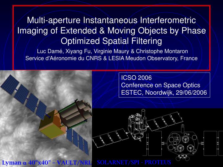
Multi-aperture Instantaneous Interferometric Imaging of Extended & Moving Objects by Phase Optimized Spatial Filtering Luc Damé, Xiyang Fu, Virginie Maury & Christophe Montaron Service d'Aéronomie du CNRS & LESIA Meudon Observatory, France.

E N D
Multi-aperture Instantaneous Interferometric Imaging of Extended & Moving Objects by Phase Optimized Spatial FilteringLuc Damé, Xiyang Fu, Virginie Maury & Christophe MontaronService d'Aéronomie du CNRS & LESIA Meudon Observatory, France ICSO 2006Conference on Space OpticsESTEC, Noordwijk, 29/06/2006 SOLARNET/SPI - PROTEUS Lyman 40"x40" – VAULT/NRL
Context – a Short History • Solar interferometry, DIRECT IMAGING OF AN EXTENDED FIELD OF VIEW in the FUV was first proposed in 1986, 20 years ago, on the EURECA platform! (on ground: ASSI table) • It was then proposed in 1989 for ESA/M2 and was selected for a Phase A on the Space Station (SIMURIS Mission with the Solar Ultraviolet Network, SUN, a 4-telescope non-redundant 2 m baseline array in rotation on the IPS) • 93: ESA/M3 as MUST/SIMURIS, a 5-telescope circular configuration and, in parallel, was studied for adaptation on the Space Station using an Hexapod support structure • In 2000, SOLARNET/SPI was proposed for ESA/F2-F3 and recommended by ESTEC review. Even if overcost, the Solar Orbiter was preferred for "political redistribution reasons"
R&D Laboratory Experiments since 1990 on Extended FOV Cophasing and Imaging • Direct cophasing at /300 of two telescopes on an extended laboratory source in 94 • Fringes and cophasing at /140 on the Sun and /220 on stars and Planets (Jupiter, Mars) in 95 and 96 (Obs. Meudon) • Stabilities up to /1000 on solar like flux and /100 on mag. 10 stars (ESA/OAST 2 - 1997) • 2000: acquisition, control and imaging with a 3-telescope cophased breadboard (laboratory setup) with measured stabilities > l/300!
SOLARNET R&D Program: Demonstrate Concept and Performances on a Representative Breadboard • Cophasing & direct imaging in laboratory in 98–2000 (measured l/300phasing) • Adaptation to direct solar observations at Meudon Observatory (Grand Sidérostat de Foucault) in 2001–2002; completion of guiding and fine pointing this spring (0.1"); cophasing l/100this summer; first images next year (filters & SDM 0.1 nm spectral resolution). SOLARNET Breadboard: more than 150 optics and detectors!
Big Issues & Next Steps • R&D • Demonstrate cophased imaging directly on the Sun • Optimize Space Qualification of Fringe Sensor • Complete integration of Focal Instrument • Programme • Prepare ESA Cosmic Vision Response (AO expected end of September)
1.5 m Towards Very High Resolution 1 m UV Interferometer: 0.02" 1 m UV “Telescope”: 0.02"?: An INTERFEROMETER rather than a large telescope: • Reduced height & mass ê small platform &launcher • Fine Pointing and thermal aspects simplified by small telescopes (use of SiC) • No need for the complex control of a large primary • Phasing and pointing ê the "Perfect" Telescope
SOLARNET is a Unique Concept of Direct Interferometric Imaging on Extended FOV • Compact Configuration: 3 telescopes of Ø350mm on 1m • Spatial Resolution of 0.025” (20–30km on the Sun in the UV) • Multi-wavelengths spectral imaging l110–400nm with a subtractive double monochromator FUV & UV, coupled to an IFTS 0.002nm
Schematic of SOLARNET Breadboard Phase measure
Cophasing in Practice Modulation Delay Line Delay Line i i i Recombination (in pupil plane on a 1mm2 diode) of the 3 beamsin 2 of the reference interferometers after spatial filtering
Recombining Cubes Modulation Delay Line Photodiodes Cophasing by Double Synchronous Detection(global WL phase shift) • 1f provides the error(zeroing method) • 2f gives the amplitude White LightInterferogram Single FrequencyDemodulation Double Frequency Demodulation
4 m Extended Source - WL - Spatial Filtering h Photodiode Filtering HolesDiameter: FT Entrance optics Diameter: FL
Phase Measure Spatial Filtering With an extented source Ø a spatial filtering is required to measure a proper contrast Simulation of the interference figure in the case of a contrasted image (granulation – not WL) Principle of a Spatial Filtering Selection Hole Filtered image Image Microscopeobjective Ø5µ Ø10µ Ø20µ Visibility 1.7%
3 base 1-3 base 2-3 1 2 base 1-2 Contrast (%) OPD (µm) 1 3 2 FOV Centering and Bias High Contrast Filtered Source
3 1 2 Reference FOV and Spatial Filtering Extreme - highly structured - source in the reduced FOV after filtering A small decentering of the reference field a (a small)in the baseline direction will produce a bias in the WLF absolute nulling OPD position of d ~ ha.When the intensity distribution is centered (SYMETRY for the 3 baselines), the contrast ismaximum on the 3 interferometers and bias is null.
3 1 2 Automatic Bias Servo • Decentering of the intensity centroïd (barycenter) of the reference field of view creates in each of the three reference interferometers a "bias" compared to zero OPD. • The two major delay lines "monitor" the phase error for B12 and B13 compared to T1 corrections and ∂12 and ∂13 available • The 3d measurement provides the "differential bias" between T2 and T3; it indicates the vertical offset pointing correction • The 2f demodulations of B21, B31 and B32 give the amplitudes; they lower with a bias; the closure error (instrumental) gives the residual horizontal correction (since vertical addressed) • Initial centering and gains are set by initial synchronous demodulation phase measure by jiggling the three active mirrors This is a multiple servo-control system as we love them!
Permanent Implementation • If the jitter is implemented on the entrance hole of the spatial filtering (e.g. at 1 KHz) by the focusing objective, the demodulation of the field centering effect (if any) can be very fast and permanent • Shortage of CNES R&D funds this year (up to now) did not allow to test the method (require object masks, improvement of the 3d interferometer electronics and 2 other synchronous detections) • We are confident on the approach, useful and fast for Earth Observation (but probably unnecessary on the Sun: reduced contrast and structuration in WL)
Miniaturization of the Reference Interferometers (Phase Measure) From a breadboard more than a meter long… 1100 mm 1500 mm … to a 15 centimeters block!
The Interferometric Binding Block of3 Reference Interferometers • It has been designed and realized • Molecular binding • 15 Homosil prisms to sub-µm & sub-arcsec precision • Invar support designed (IDEAS modeling: 0.8 MPA and 2" for ± 5° tolerance) and awaiting realization (test this autumn?)
It is more than appropriate to pursue the effort R&D Status • R&D is necessary prior to accepted project to validate hard points and consolidate mission profile so as to prepare competitive response with SCIENTIFIC and TECHNICAL original content • We have more than 20 years of experience with fringes stabili-zation by synchronous detection (simple and double and, now, with controlled optimization of selective spatial filtering) - and, among them, 10 on the phasing for true imaging on a large FOV • We have developed an optimum technique to phase multiple telescopes on the SAME extended FOV, even is contrasted and mobile (scanned)
Conclusions & Perspectives • We have demonstrated 3-telescope cophasing and imaging in laboratory and we expect to extend the demonstration to the Sun this summer • Both acquisition and tracking are monitored by our method, and the three levels of servo-control are smoothly interacting: guiding of Siderostat (Platform), fine pointing and optimized cophasing on a self referenced external extended source • Extension to Earth Observation (LEO or GEO) is straightforward since acquisition and tracking on an Extended source in White Light are similar to the Solar case. Further, a 5 x Ø2 m circular configuration would fit an Ariane V… This Very High Resolution Interferometry Mission would be possible NOW for a launch in 2012 (as a CNES minisatellite) for the next solar maximum or in 2016 (Cosmic Vision Proposal) in complement or replacement of SO. EU, US, Indian and Chinese contributions are discussed.
Thank you! J.-F. Hochedez David Berghmans Frédéric Clette Steven Dewitte Werner Curdt Eckart Marsch Volker Bothmer Richard Harrison Philippe Lamy Serge Koutchmy Eric Quémerais Rosine Lallement Siraj Hasan Guoxiang Ai S. Turck-Chieze Patrick Boumier Tahar Amari Brigitte Schmieder J.M. Malherbe Guillaume Aulanier Pascal Démoulin Silvano Fineschi J. Trujillo-Bueno James Klimchuk Angelos Vourlidas Ted Tarbell