Download
1 / 1
10 likes | 238 Vues
BRUX: A New EPN and IGS Reference Station in Brussels C. Bruyninx , W. Aerts, P. Defraigne, J. Legrand Royal Observatory of Belgium, Av. Circulaire 3, Brussels, Belgium, C.Bruyninx@oma.be P. De Doncker, D. Lafourte National Geographic Institute, Abdij ter Kameren 5, Brussels, Belgium.

E N D
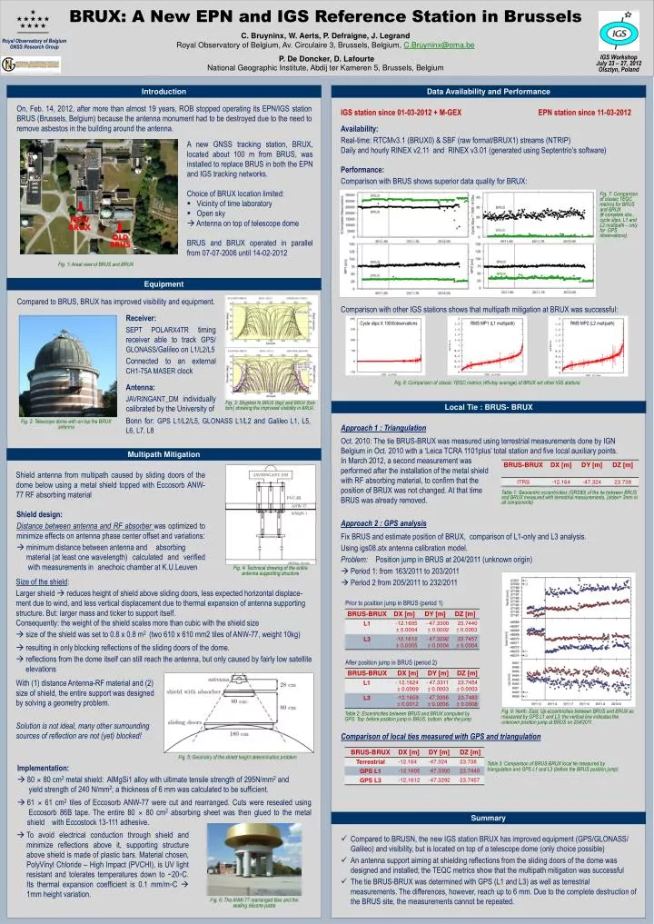
BRUX: A New EPN and IGS Reference Station in Brussels C. Bruyninx, W. Aerts, P. Defraigne, J. Legrand Royal Observatory of Belgium, Av. Circulaire 3, Brussels, Belgium, C.Bruyninx@oma.be P. De Doncker, D. Lafourte National Geographic Institute, Abdij ter Kameren 5, Brussels, Belgium Royal Observatory of Belgium GNSS Research Group IGS Workshop July 23 – 27, 2012 Olsztyn, Poland Introduction Data Availability and Performance On, Feb. 14, 2012, after more than almost 19 years, ROB stopped operating its EPN/IGS station BRUS (Brussels, Belgium) because the antenna monument had to be destroyed due to the need to remove asbestos in the building around the antenna. IGS station since 01-03-2012 + M-GEX EPN station since 11-03-2012 Availability: Real-time: RTCMv3.1 (BRUX0) & SBF (raw format/BRUX1) streams (NTRIP) Daily and hourly RINEX v2.11 and RINEX v3.01 (generated using Septentrio’s software) Performance: Comparison with BRUS shows superior data quality for BRUX: Comparison with other IGS stations shows that multipath mitigation at BRUX was successful: • A new GNSS tracking station, BRUX, located about 100 m from BRUS, was installed to replace BRUS in both the EPN and IGS tracking networks. • Choice of BRUX location limited: • Vicinity of time laboratory • Open sky • Antenna on top of telescope dome • BRUS and BRUX operated in parallel from 07-07-2006 until 14-02-2012 Fig. 7: Comparison of classic TEQC metrics for BRUS and BRUX (# complete obs., cycle slips, L1 and L2 multipath – only for GPS observations). Fig. 1: Areal view of BRUS and BRUX NEW BRUX OLD BRUS Equipment Compared to BRUS, BRUX has improved visibility and equipment. Receiver: SEPT POLARX4TR timing receiver able to track GPS/ GLONASS/Galileo on L1/L2/L5 Connected to an external CH1-75A MASER clock Antenna: JAVRINGANT_DM individually calibrated by the University of Cycle slips X 1000/observations RMS MP1 (L1 multipath) RMS MP2 (L2 multipath) Fig. 8: Comparison of classic TEQC metrics (45-day average) of BRUX wrt other IGS stations Fig. 3: Skyplots fo BRUS (top) and BRUX (bot-tom) showing the improved visibility in BRUX. Local Tie : BRUS- BRUX Bonn for: GPS L1/L2/L5, GLONASS L1/L2 and Galileo L1, L5, L6, L7, L8 Fig. 2: Telescope dome with on top the BRUX antenna Approach 1 : Triangulation Oct. 2010: The tie BRUS-BRUX was measured using terrestrial measurements done by IGN Belgium in Oct. 2010 with a ‘Leica TCRA 1101plus’ total station and five local auxiliary points. In March 2012, a second measurement was performed after the installation of the metal shield with RF absorbing material, to confirm that the position of BRUX was not changed. At that time BRUS was already removed. Multipath Mitigation Shield antenna from multipath caused by sliding doors of the dome below using a metal shield topped with Eccosorb ANW-77 RF absorbing material Table 1: Geocentric eccentricities (GRS80) of the tie between BRUS and BRUX measured with terrestrial measurements. (stdev= 3mm in all components) • Shield design: • Distance between antenna and RF absorber was optimized to minimize effects on antenna phase center offset and variations: • minimum distance between antenna and absorbing material (at least one wavelength) calculated and verified with measurements in anechoic chamber at K.U.Leuven • Approach 2 : GPS analysis • Fix BRUS and estimate position of BRUX, comparison of L1-only and L3 analysis. • Using igs08.atx antenna calibration model. • Problem: Position jump in BRUS at 204/2011 (unknown origin) • Period 1: from 163/2011 to 203/2011 • Period 2 from 205/2011 to 232/2011 • Comparison of local ties measured with GPS and triangulation Fig. 4: Technical drawing of the entire antenna supporting structure • Size of the shield: • Larger shield reduces height of shield above sliding doors, less expected horizontal displace-ment due to wind, and less vertical displacement due to thermal expansion of antenna supporting structure. But: larger mass and ticker to support itself. • Consequently: the weight of the shield scales more than cubic with the shield size • size of the shield was set to 0.8 x 0.8 m2 (two 610 x 610 mm2 tiles of ANW-77, weight 10kg) • resulting in only blocking reflections of the sliding doors of the dome. • reflections from the dome itself can still reach the antenna, but only caused by fairly low satellite elevations Prior to position jump in BRUS (period 1) After position jump in BRUS (period 2) With (1) distance Antenna-RF material and (2) size of shield, the entire support was designed by solving a geometry problem. Solution is not ideal, many other surrounding sources of reflection are not (yet) blocked! Fig. 9: North, East, Up eccentricities between BRUS and BRUX as measured by GPS L1 and L3; the vertical line indicates the unknown position jump at BRUS on 204/2011. Table 2: Eccentricities between BRUS and BRUX computed by GPS. Top: before position jump in BRUS, bottom: after the jump. • Implementation: • 80 × 80 cm2 metal shield: AlMgSi1 alloy with ultimate tensile strength of 295N/mm2 and • yield strength of 240 N/mm2; a thickness of 6 mm was calculated to be sufficient. • 61 × 61 cm2 tiles of Eccosorb ANW-77 were cut and rearranged. Cuts were resealed using Eccosorb 86B tape. The entire 80 × 80 cm2 absorbing sheet was then glued to the metal shield with Eccostock 13-111 adhesive. Fig. 5: Geometry of the shield height determination problem Table 3: Comparison of BRUS-BRUX local tie measured by triangulation and GPS L1 and L3 (before the BRUS position jump) Summary • To avoid electrical conduction through shield and minimize reflections above it, supporting structure above shield is made of plastic bars. Material chosen, PolyVinyl Chloride – High Impact (PVCHI), is UV light resistant and tolerates temperatures down to −20◦C. Its thermal expansion coefficient is 0.1 mm/m◦C 1mm height variation. • Compared to BRUSN, the new IGS station BRUX has improved equipment (GPS/GLONASS/ Galileo) and visibility, but is located on top of a telescope dome (only choice possible) • An antenna support aiming at shielding reflections from the sliding doors of the dome was designed and installed; the TEQC metrics show that the multipath mitigation was successful • The tie BRUS-BRUX was determined with GPS (L1 and L3) as well as terrestrial measurements. The differences, however, reach up to 6 mm. Due to the complete destruction of the BRUS site, the measurements cannot be repeated. Fig. 6: The ANW-77 rearranged tiles and the sealing silicone paste