Download
1 / 49
640 likes | 1.21k Vues
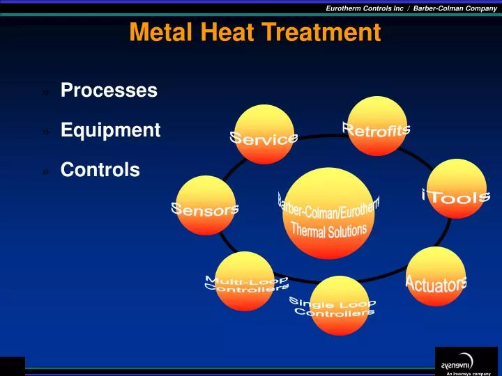
Metal Heat Treatment. Processes Equipment Controls. Retrofits. Service. iTools. Barber-Colman/Eurotherm Thermal Solutions. Sensors. Actuators. Multi-Loop Controllers. Single Loop Controllers. THE HEAT TREATING PROCESS. Heat treated components are essential to the operation of…

E N D
Metal Heat Treatment • Processes • Equipment • Controls Retrofits Service iTools Barber-Colman/Eurotherm Thermal Solutions Sensors Actuators Multi-Loop Controllers Single Loop Controllers
THE HEAT TREATING PROCESS • Heat treated components are essential to the operation of… • automobile, aircraft, spacecraft, computers, heavy equipment of every kind, wood working tools, bearings, axles, fasteners, camshafts, cutting tools, gears, etc. • vast majority of material heat treated is iron & steel • alloys of aluminum, copper, magnesium, nickel, and titanium may also be heat treated
THE HEAT TREATING PROCESS • metal components are heated & cooled under tight controls • improves properties, performance & durability • can soften the metal - improve formability • can harden the metal - improve strength • can put a hard surface on relatively soft metal - improve abrasion (wear) resistance • can create a corrosion - resistant skin… inhibits corrosion • can toughen brittle products
THE HEAT TREATING PROCESS Requires three basic steps: • heating to a specific temperature • holding (soaking) at that temperature for the appropriate time • cooling according to a prescribed method • heating temperature range to 24000F (1316 °C) • soaking times vary from a few seconds to 3 to 4 days • cooling may be slowly in the furnace or quickly (quenched) into water, brine, oils, polymer solutions, molten salts, molten metals or gases • 90% of metal parts are quenched in water, oil, polymers, or gases
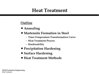
ANNEALING • heat material for several hours at elevated temperatures (20000F) (1093°C) • control slow cooling • facilitates cold working & machining, improves ductility and some electrical properties and promotes dimensional stability STRESS-RELIEF • heat material for several hours at an intermediate temperature (12500F) (677°C) • control cooling • removes stresses resulting from processes such as cold working, casting, forging, or welding
NORMALIZING • heat material at elevated temperatures for varying time soaks • control cool in air • results in homogeneous microstructure - provides better machinability & more uniform properties QUENCH HARDENING • primary heat treating process for strengthening steel components • heat material to an elevated temperature (16000F) (871°C) • rapid quench to develop hardness • this is followed by TEMPERING… • reheat material to a low temperature (4000F) (204°C) to develop specific mechanical properties, to relieve quench stresses and to insure dimensional stability
GAS CARBURIZING • heat material at elevated temperatures (to 18500F) (1010°C)for varying soak times (dependent on case depth requirement) • while soaking, provide a high carbon atmosphere source from a hydrocarbon gas such as methane (natural gas) or propane • resulting chemical combination vs. the gaseous carbon and the iron, from the steel components provides an iron carbide compound on the surface • high carbon surface layer is called “case” • typical case depths vary from .010” to .150” • furnace cool to stabilizing temperature (15500F) (843°C)for varying soak times • rapid quench to develop high case hardness and desired core properties • temper by re-heating to a low temperature (3500F) (177°C)to develop specific case and core properties, to relieve quench stresses and to insure dimensional stability
CASE DEPTH • Case is accomplished by carburizing and quenching • The objective is to provide a hard wear resistant surface layer and maintain a softer core • Case depth is typically measured in thousandths of an inch (.037in). • Typical range specs are .018” to .025”, .032” to .038”, .038” to .045” etc. • Case depth is generally measured as the depth of penetration from the surface with a hardness above Rc 50 or carbon concentration above .40 C
STEEL GRADES Grades of Steel Typically Heat Treated 1000, 1100, 1200, 1300, 1500 4000, 4100, 4600, 5100, 6100 8600, 9300 series 1040 = .37 to .44 carbon content Standard carbon steel 8620 = .18 to .23 carbon content Carburizing grade alloy steel
CARBURIZING • Provides abundant supply of carbon for absorption into surface of steel • Provides increased carbon and hardness to surface of steel • Case depth is time and temperature dependent • At 1700°F (927°C) and .9%C settings using a conventional 40% Nitrogen , 40% Hydrogen, and 20% Carbon Monoxide in an Endothermic atmosphere: AfterAchieveEffective Case 1 hour .62C .012” 4 hours .71C .026” 20 hours .86C .061”
Heat Treating Solutions Simple Boost and Diffuse
CARBONITRIDING • Heat material at elevated temperatures (16500F) (899°C) for varying soak times (dependent on case depth requirement) • while soaking, provide a high carbon atmosphere source from a hydrocarbon gas such as methane (natural gas) or propane AND a high nitrogen containing gas (ammonia) • resulting chemical combination vs the gaseous carbon, nitrogen, and the iron, from the steel components provides an iron carbide/nitride compound on the surface • high carbon/nitrogen surface layer is called “case” • furnace cool to stabilizing temperature (15500F) (843°C) for minimal soak time • rapid quench to develop high case hardness and desired core properties • temper by reheating to a low temperature (3000F) (149°C)to develop specific case and core properties, to relieve quench stresses and to insure dimensional stability
HEAT TREATING SOLUTIONS CarboNitriding
EQUIPMENT • most components are heat treated in furnaces • most furnaces heated with natural gas fuel - some electric • two broad categories of furnaces… • BATCH and CONTINUOUS • in batch, material is charged/discharged as a single unit or batch • in continuous, material is conveyed automatically, providing a constant flow
EQUIPMENT BATCH • consists of insulated chamber with external steel shell • has a heating system for the processing chamber • has one or more doors providing access and sealing of the chamber • may have internal quench tank or slow cool vestibule • typically has automated controls
EQUIPMENT CONTINUOUS • same basic components as Batch, but… • has means of conveying material through the process zones • some types are PUSHERS, BELT or chain conveyors, ROLLER HEARTH, SHAKER HEARTH, ROTARY HEARTH, ROTARY RETORT and WALKING BEAM • has a multi-zone heating system for the processing chamber(s) • has doors or screens providing access and isolation • typically has multi-loop automated controls • size ranges from 100’s lbs/hr to ± 10000 lbs/hr • some continuous may have automated, self-contained quenching capability
EQUIPMENT HEATING METHODS • Open-fired furnaces fuel-gas air mixture combustion burns directly into heating chamber material may be protected from oxidation and/or products of combustion by passing through a MUFFLE or RETORT. • Radiant tube furnace fuel-gas air mixture combustion circulates inside radiant tubes. Heat is radiated through the tube walls into the heating chamber. Radiant tubes are nickel alloy, ceramic or occasionally silicon carbide • Electric heating elements, 2 basic methods… exposed - open to heating chamber environment indirect - isolated from chamber by insertion into radiant tube(s) elements are typically Ni - Cr alloy in wire, rod, ribbon or sheetmetal form
EQUIPMENT QUENCHING METHODS • most common quenching media are water, oil, or molten salt • fastest cooling rate results from spraying refrigerated water under pressure • quench tanks vary widely in capacity and design • many are equipped with variable agitation, heating and cooling, filtering and ventilation • up-to-date monitoring equipment may include computer controls and sensors to monitor temperature, chemistry, specific gravity and pressure
EQUIPMENT NEW FURNACE HARDWARE TECHNOLOGY • driven by desire to cut costs, improve production, reduce environmental impact • computer modeling has promoted improved design and construction • recuperated combustion systems are more efficient and burner design has been optimized • insulating brick has been replaced with ceramic fiber linings • chamber shapes have been modified and improved • reliable in-situ sensors provide valuable feed back about temperature and atmosphere composition • state-of-the-art controls facilitate computer integrated management systems
ENDOTHERMIC GENERATOR • Endo generator creates the atmosphere that provides a positive pressure in a heat treating furnace, and a platform on which a carburizing environment can be formulated by the addition of enriching gas or dilution air. An endothermic generator consists of: • Heating Chamber – operating temp ± 1925°F (1052°C) • One or more retorts containing… • Numerous small, porous, ceramic pieces, impregnated with nickel as a catalyst for the reaction. • A cooling heat exchanger to rapidly cool the products to a temperature that will not allow the reaction to proceed further
ENDOTHERMIC ATMOSPHERE • A carrier gas provides a positive pressure in a heat treating furnace and a mechanism to carburize or decarburize by adding oxygen or methane • 40% Nitrogen – 40% Hydrogen – 20% Carbon Monoxide (CO) – and .1 Carbon Dioxide (CO2) • Nickel Catalyst ± 1925°F (1052°C) • Air and Methane in a ratio of 2.75 to 1 is heated to 1900°F (1038°C) to 1950°F (1066°C) and flowed across nickel-impregnated cubes (catalyst) to produce Endothermic gas • Measured and controlled in dew point – typical set point is 40°F
ENDOTHERMIC ATMOSPHERE • At 1700°F (927°C) with a 20% CO endothermic atmosphere .40%C = 400F D.P. .60%C = 280F .80%C = 200F 1.00%C = 130F • At 15500F (843°C) with a 20% CO endothermic atmosphere .30%C = 660F D.P. .50%C = 500F D.P. .70%C = 400F D.P.
SHIM STOCK INSERTION ASSEMBLY • Shim stock carbon determination is the only true measurement of carbon potential in a heat-treating furnace. • Other devices such as O2 probes and infrared are inferential measurements, which do not measure carbon directly. • The Low carbon steel shim is cleaned, and weighed to four decimal places and then inserted into the furnace through the assembly. • Once inserted, the shim reaches equilibrium which is a function of time and temperature. • When equilibrium is met the shim is pulled back into the assembly to cool. • The shim is then removed and weighed to determine its carbon content. • This method of carbon measurement is not practical for control although it provides a true measurement of actual carbon which serves as verification of the instrument calculation.
OXYGEN PROBE OUTPUT • Oxygen (carbon) sensors generate a (EMF) millivolt signal which corresponds to the partial pressure of oxygen in the furnace. • As the temperature increases the probe impedance will decrease and around 900oF the probe will begin to generate a mV signal which will correspond to the O2 partial pressure differential. • At 1700 degrees the probe output is 1150 mV which represents 1.0% carbon in an atmosphere with 20% CO. • The actual carbon value is calculated by solving the carbon equation resident in the microprocessor. • The lower the oxygen concentration the more responsive the probe becomes. The actual oxygen content in a typical carburizing atmosphere is 1 billionth of 1 billionth of one percent.
OXYGEN PROBE MILLIVOLT OUTPUT • The usable output range of the probe for an endothermic atmosphere is between 1000 and 1250 mV.
ATMOSPHERE COMPOSITION • The components of conventional endothermic atmosphere are 40% hydrogen, 40% nitrogen, and 20% carbon monoxide. • As illustrated when the CO value decreases in the furnace the CO2 value will increase. • This is also similar for the generator where the hydrogen decreases the water vapor (H20) will also increase.
ATMOSPHERE COMPOSITION Atmosphere at 40oF DP provides different %C at different temperatures. Example: 1500oF = .75%C 1600oF = .60%C 1700oF = .40%C For carbon potential above saturation sooting will occur and non-controlled carburizing will take place resulting poor quality work.
PROBE TECHNOLOGY SPRAYED AREA CONTACT ANODE • The sprayed on electrode was designed by Kent instruments in the 70’s and is still being used by some manufacturers today such as MMI and Kent. • As indicated the isolated external electrode (nickel-chrome alloy) is flame sprayed onto the tip of a solid slip cast Zirconia tube. The positive electrode is spring loaded internally to the Zirconia tube. • This design is expensive to build and inconsistent in quality due to the complexity of manufacturing. • The sprayed electrode over time will crack and then peel as a result of the thermal cycling and different coefficients of expansion of the materials in intimate contact.
PROBE TECHNOLOGY SIRO AREA CONTACT ANODE • The Csiro probe (known as the siro sensor) is the most widely used probe design in the industry. • The government of Australia currently holds the now expired patent for the design of the ceramic substrate and is the supplier/licensor to several manufacturers. • This substrate is constructed with an alumina tube into which a Zirconia plug is pressed into one end and sealed, using a eutectic ceramic cement. • Over time, cycling of temperature will cause cracks to develop in the cemented junction. • When a crack occurs, furnace atmosphere will ingress into the cell and contaminate the reference air, causing inaccuracies in the output of the sensor.
PROBE TECHNOLOGY LINE CONTACT ANODE • The line contact design utilizes slip cast Zirconia with a spring loaded contact to the outer sheath as the external electrode/conductor. • Although slightly more expensive to build, the gas tight slip cast Zirconia tube has been proven to facilitate the most reliable probe configuration on the market. • This particular design uses knife-edge contacts which will precipitate cracks in the Zirconia during thermal expansion and contraction typical in batch furnace applications. • This particular manufacturer’s design incorporates 10 large holes located near the tip of the electrode. Due to the location and the large number of holes, effective Probe conditioning (Burnoff) is virtually impossible.
VIRTUAL POINT CONTACT ANODE • This probe takes advantage of the reliability of the gas tight slip cast Zirconia tube design. • Virtual point contact reduces the potential of stress fractures and also provides a lower resistance at the outer electrode interface. • sheaths utilizes a cermet coating which minimizes the catalytic reaction between methane and nickel typically observed with alloy materials exposed to reducing furnace atmosphere. As a result less soot is deposited, degradation of the sheath is reduced, and probe life is extended.
OPEN vs. CLOSED SHEATH Probe Burnoff Required? Probe Burnoff Required
TYPICAL PROBE INSTALLATION Two to Four inch Insertion
Probe Conditioning The purple and green pen represent the millivolt probe output on different scales. The red pen represents the probe thermocouple. Summary: During burnoff the probe output should drop below 200 mV. As shown by green pen.