Download
1 / 19
190 likes | 389 Vues
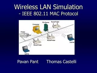
An Empirical Analysis of the IEEE 802.11 MAC Layer Handoff Process. Arunesh Mishra Minho Shin William Arbaugh University of Maryland,College Park,MD. The IEEE 802.11 Wireless LAN architecture. Wireless LAN Station (STA) Access Points (AP) Basic Service Set (BSS) Distribution System (DS)

E N D
An Empirical Analysis of the IEEE 802.11 MAC Layer Handoff Process Arunesh Mishra Minho Shin William Arbaugh University of Maryland,College Park,MD
The IEEE 802.11 Wireless LAN architecture • Wireless LAN Station (STA) • Access Points (AP) • Basic Service Set (BSS) • Distribution System (DS) • Extended Service Set (ESS).
The IEEE 802.11 Wireless LAN architecture • Two different ways to configure a network • Ad-hoc • No structure • Every node can talk to each other • Infrastructure • Fixed APs with which mobile nodes can communicate • APs are connected to DS
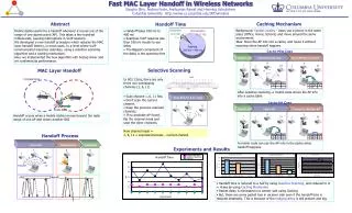
Definition : A Handoff occurs when a mobile station moves beyond the radio range of one AP,and enter another BSS(at the MAC layer). [transfer of physical layer connectivity and state information from one AP to another with respect to the station in consideration] • During handoff, management frames are exchanged between the STA and the AP.The AP involved may exchange certain context information (credentials) specific to the station. (IAPP or propriety protocol) • Problem : Latency (the STA is unable to send or receive traffic during handoff)
Handoff Procedure • Mobile node moves from coverage area of one AP to that of another AP • Steps During Handoff • Discovery • Initiation and scanning phase (accomplished by MAC layer function :scan) • During a scan, the card listens for beacon messages (sent out periodically by APs at a rate of 10 ms), on assigned channels. Thus the station can create a list of APs prioritized by the received signal strength. • Active and passive scanning mode
Handoff Procedure (cont.) • Reauthentication • Authentication and re-association • The reauthentication phase involves the transfer of credentials and other state information from the old-AP. As mentioned earlier, this can be achieved through a protocol such as IAPP . • Sequence of messages exchanged between the mobile node and the participating APs. • Probe • Authentication • Reassociation
Handoff Procedure (cont.) Probe Delay: Messages A to E are the probe messages from an active scan. The latency for this process is called probe delay. The actual number of messages during the probe process may vary from 3 to 11. Authentication Delay: This is the latency incurred during the exchange of the authentication frames (messages E and F ). Authentication consists of two or four consecutive frames depending on the authentication method used by the AP. Reassociation Delay: This is the latency incurred during the exchange of the reassociation frames (messages G and H ). Upon successful authentication process, the station sends a reassociation request frame to the AP and receives a reassociation response frame and completes the handoff.
Experimental Conditions • The measurements are done on two co-existing wireless networks (utilizing APs from two popular vendors), and using three wireless NICs from different vendors. • In building wireless networks • 83.5 MHz from 2.4000 GHz to 2.4835 GHz (802.11b) • 11 channels, each channel being 22 MHz in width, and each channel centered at 5 MHz intervals • Management frame used during handoff are captured by the sniffer
Results and analysis Handoff Latencies Graph for different client using Lucent AP 1.Probe delay is dominating component (90%) : Its good to use technique/heuristics that either cache or deduce AP information without having to actually perform a complete active scan stands to benefit.
Results and analysis (cont.) Handoff Latencies Graph for different client using Cisco AP 2.Wireless hardware used(AP,STA) affects the handoff latency : Keeping fixed AP it seen that client card affects the latency. (Fig11)
Results and analysis (cont.) 3.Keeping the client card fixed,the AP also affects the latency but to a much lower extent. 4.There are large variation in the handoff latency (Fig. 13) 5.Different wireless cards follow different sequence of messages
Results and analysis (cont.) • Further analysis of Probe(its contribution to delay is maximum) • Probe is essentially a active scan,the wireless NIC do by default • Transmit a probe request frame which contains the broadcast address as the destination. • Start a probe timer. • Listen for probe response. • If no response received by minChannelTime, scan next channel. • If one or more responses are received by minChannelTime, stop accepting probe responses at maxChannelTime and process all received responses. • Move to next channel and repeat above steps.
Results and analysis (cont.) The scatter-plot shows two clusters being formed,which more-or-less correspond to the MinChannelTime and MaxChannelTime values from the above active scan procedure.
Results and analysis (cont.) If there are two or less probe responses,wait time is between 0-20ms,otherwise its between 35 to 40ms.Number of probe response can createa difference of average of 25ms per channel.
Results and analysis (cont.) The distribution of the probe-wait time has a definite positive correlation (in direct proportion) with the number of probe response messages received. For the same number of probe responses, the distribution of the probe wait time depends on the particular heuristic used by the client card. For instance, the Cisco card has values clustered around two parameters while the Lucent card has a near-uniform distribution. ---------------------------------------------------------------------------- Heuristics that require the least number of active scans will perform the best. The following methods (or a combination of them) might be used to design heuristics and these are all attempts to avoid an active scan:
Results and analysis (cont.) 1. Query an external agent that provides hints on the neighboring APs and channels i.e a map of the APs based on the location. 2. Interleave scan messages with data during normal connectivity and use that information to perform a partial active scan (or no scan at all) during the handoff. Also passive scanning (listening for beacon messages) might be performed during normal connectivity to build up the list of APs. 3. Since the probe-wait time depends on the number of probe responses received, another strategy might be to create an ordering among the APs such that a single AP or a small set of APs is responsible for probe requests (i.e. the number of probe responses is a constant).
Conclusion • Probe delay accounts for more than 99% of overall handoff latency • Current WLAN equipment will not meet the expectations (replacing or augment 4G systems) that many have.Handoff latencies the authors measured is much more then the guidelines for jitter in voice over IP applications ( latency is recommended not to exceed 50ms) • Significant variation in handoff latency with change in APs SSID and channel • Smallest handoff latency when APs have same SSID and are on same channel