Download
1 / 155
1.55k likes | 1.67k Vues
Training Guide. Working with Build!IT 2.3.2 June 2011. Itinerary. Day One Graphical User Interface Menu Bar, Tool Box, Mode Bar, Dialog Box and View Manipulations. Understanding Projects and Managing files Setting up the Measurement Device

E N D
Training Guide Working with Build!IT 2.3.2 June 2011
Itinerary Day One • Graphical User Interface • Menu Bar, Tool Box, Mode Bar, Dialog Box and View Manipulations. • Understanding Projects and Managing files • Setting up the Measurement Device • Opening CAD Files, Picking a Device, Logging it in, Measurement settings • Coordinate Systems • Alignment Tools • Understanding the various alignment tools and techniques.
Itinerary Day Two • Advanced Measurements • Cylinders, Spheres, Points and Point Clouds • Inspection and Reporting • Inspect Real-Time • Inspect Hole • Surface to Cloud Analysis • Reporting Measured Data • Basic Geometry Creation • Creating and Editing Geometry • Tool Building • General Workflow • Creating and Placing Details
Itinerary Day Three • Advanced Alignments • Changing Device locations • Alignment points to surface pairs • Combined Alignment Techniques • Combine device measurements • BAE Specifics
Concepts and Interface Introduction • Build!IT has the ability to download engineering data directly from the CAD system into Build!IT. Designers can use Build!IT to view CAD Parts in a 3-D environment permitting them to no longer rely on large, expensive blue prints to examine designs. • Build!IT can also gather point information and perform many of the tasks involved with the reverse engineering of old production tooling. If there is a need for advanced reverse engineering tools, you can use products similar to Imageware’s Surfacer to complete these tasks that require additional surfaces and modification work.
Introduction to Build!IT Build!IT : • Is easy to remember even after periods of non-use • Will run multiple hardware systems • Has a work flow that is familiar to users • Eliminates the need for additional machining to set details • Allows real-time surface inspection • Provides seamless transfer of 3D data
User Interface • Menu Bar • Pull-down • Pull-right • Message Area • Help • Dialog Boxes • Viewport /Graphics Area • World Axes • Tool Bar • Mode Bar • Heading • Gray vs. Colored Icons/Menus
File Operations • Open • This command is used to open a new CAD File. Opening a new CAD file will force you to close the current CAD file. • Job Info • Used to store specific information about a job. This information will automatically be put in all reports generated in Build!IT. • Save • This function will save work that was done during a Build!IT session. • Import • Used to load additional data, such as CAD files or reference point data.
Typical Build!IT Dialog Box • Heading • Active Panel • Interactions • Selection List • Radio Buttons • Slider Bar • Input Box • Drop-down list • Check Box • Apply • Closing Dialog Boxes • Multiple Dialog Boxes
View Controls View | put in no show • Put in No Show • Use this command to hide an object by placing it in the No Show view. When toggled to the No Show view, use it to send an object back to the Show view. Toggle Show / No Show • Visibility • Objects placed in the no show state are hidden from normal viewing. To view the objects in the no show view or to unhide an object use the View>Toggle Show/NoShow command. View | toggle show / no show
View Controls • Set Center • Using this command will allow you to pick a point in the view that will become the new center of the view port. • Rotate • Select the Rotate icon then click and hold the left mouse button in the graphic area of the view port. Move the mouse around on the screen to make the rotation. • Translate • Select the translate icon then click and hold the left mouse button in the graphic area of the view port. Move the mouse around on the screen to make the movement. • Fill Screen • Picking this icon will force the displayed objects to fill the entire view port. • Zoom • There are two modes to the zoom function: • Zoom Rectangle – Used to dynamically select the area of the view port that will be enlarged. • Zoom in / Out – Used to enlarge or reduce the viewport’s volume by clicking the left mouse button or right mouse button respectively.
Display Modes • There are different display options available for each type of entity (point, curve, or surface). • Display settings changed using this dialog box are saved only for your current work session. • With the Display Mode dialog box you can change single or multiple entities by making selections from the list or picking in the viewport. • To limit the contents of the displayed list or make it easier to pick certain items in the viewport, be sure to use the “Interactions” palette.
Display Modes Parameters Supply the following information for the operation: • Selected objects • Point style • Point size • Surface mode • Surface Resolution • Divisions U/V • Curve width • Polygon Style • Show label • Visible • Colour
Hiding Surfaces by their size View | Surfaces | Hide by Size Changes the visibility of the selected surfaces based on a user-defined radius size. This is particularly helpful for cleaning files after downloading from third party software applications. • Surfaces - Pick the surfaces on which to perform the operation. See Full Surface List. • Radius Threshold - Enter the radius size to use for hiding the selected surfaces. See Distance Data Type. • Change Visibility of Surfaces - Indicate whether you would like to hide all surfaces with a radius smaller than threshold or greater than threshold. See Enumerated Data Type. • Visible - Indicate whether to hide or show the surfaces in the designated range.
Making Surfaces Transparent View | Surfaces | Transparent • Renders all visible surfaces in semi-transparent mode. In transparent mode you can see through the surfaces to view any data that may otherwise be obscured. • Note: You can set the default transparency value using the Surfaces tab on the System|View Preferences dialog box.
Workshop • Exercise 1A: • View Controls
How to organize a project Job Check list The following are questions you should ask yourself or the customer before starting any project in BuildIT • What is the purpose of the project? • Building • Inspection • Reverse Engineering • Is there CAD data available? • CAD format type used. • Is the reference point data separate? • If it is separate what format is it? • What is the Project Information? • Job Name/Number • Designer • Job originator • What level of accuracy is needed? • Very accurate (0.001 - 0.005 or 0.0254-0.127 mm) • Accurate (0.005 - 0.010" or 0.127-0.254 mm) • Moderate (0.010 - 0.020" or 0.254-0.508 mm) • Coarse (0.020 - above or 0.5 mm and above)
How to organize a project • What type of device will be used? • Laser Tracker • Touch Probe (Portable CMM) • Which alignment technique will be used? • Datum/Feature based • Point Cloud to Surface • What form of reporting is needed? • Printed • Color plots • Screen Shots • What format does the job need to be saved in? • Translated to CAD • IGES • Native BuildIT format (.imw)
Store the transformation In Build!IT – start a new job Start measurement device If needed add tolerances to design points Store points and print reports Import CAD model Create point details Create measured points from reference points Build point details Start transformation of measured coordinate system to the tool’s CAD coordinate system Save and close Evaluate the transformation and correct if necessary Setting up for a job The Build Process with Build!IT • With Build!IT, the build process is simplified. You are always building to the latest generation of the design because the link to the digital master is maintained. This almost eliminates the need for manual input and results in a reduced potential for error • General workflow for the build process is as follows:
Importing a CAD File Setting file units • When reading in point data it is important to assure that the file units are set correctly, most simple forms of point data are unitless which means that the file contains no indicator of what measurement units were used by the device collecting the data. If a point cloud measured in millimeters were opened into BuildIT set to Inches, then any points would be created in the same value for inches not millimeters. • To set the preferred units, go to; System/System Preferences Preparing model for inspection • Check scale • Delete what is not needed. • Check surface normal vectors for consistency.
Importing a CAD File Different point types. • Reference Points • Reference points which are used for creating coordinate alignments, can come from any source: they could come from an existing CAD file, or they could be imported from a separate text file like for example an Excel spread sheet or taken off of a blue print and entered in a simple electronic text file such as Notepad. Let s look at the formats of these files and the required settings for this data type • Design Points • Designed points are points which are used to place BuildIT details, the primary difference between a design point and a reference point is that design points contain allowable tolerances associated with the placement of tooling details. The source of these tolerances can come from a cad system which is capable of exporting this data, or the tolerances can be manually entered by using the edit reference point command or the convert to reference point command and specifying the required tolerances. • Measured • A measured point or cloud of points are created by using any of the measurement commands such as measure point or measure circle.
How to import points File Preference Settings • When a file is opened or imported into Build!IT it s structure is determined by the System>File Preference settings. Data Delimiting Character • The Data Delimiting Character Set is the character in the ASCII file that is seen as the separator for the X,Y and Z values for each point. If you are reading reference point data it is also the separator for the point label and its associated tolerances. Scan Line Delimiter • The Scan Line Delimiter Character is an item that represents the end of a line of points in a point cloud, this will allow for subsets of points within a cloud and is helpful when collecting a scan line cloud for the purpose of reverse engineering.
How to Define Reference Points • Defining Points • The command for creating Reference Points is located under Tools>Create Point>Coordinates • Point Name and Number • These fields are used to enter the name and number of the reference point to be created. • Point • The X,Y,Z values can be entered here, or the Interactions can be used to create a point from CAD data. • To use the CAD data to create the reference point, click on the label Point to activate that panel. • Next, select the Interactions button at the lower left of the dialog box.
How to Define Reference Points • Note that the options on the tool bar are dependent on the objects displayed in the view port; • For example, if no curves were in the view port, the tool bar would appear like this. • To create a reference point at the center of a bushing hole, click on the Circle or Arc Center interaction.
How to Define Reference Points • If the Reference Point will be located with a nest or adapter, the offset for the adapter can be entered in the Offset panel. • Existing Reference points can be edited by using the command Edit>Reference Point Editor .
Organising your model Object names and numbers • All objects in BuildIT have a unique name, this name can be used to modify the object for the purpose of displaying we re changing the objects appearance. An object name can contain up to 64 characters and any type of character is allowed; however be careful using certain characters may not be appropriate for downstream applications. • For the purpose of using the Best Fit Point Pairs alignment command you should maintain an alphanumeric naming convention for your reference and measured points, the naming convention should contain up to three characters for the points group specification and a number to specify that points position in the group. For example ERS 12 the three letters identify the group, in this case Enhanced Reference System, point number twelve. Using Colors • BuildIT has the ability to display an object based on its color, you can either toggle the display on or off of an object by using the show/NoShow by color command. Using groups • Sometimes it might be convenient to group different objects to control their visibility based on their grouping. The create group command can be used to identify a group of objects.
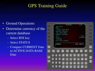
Using a Measurement Device List of supported devices • FARO/SMX Tracker • Leica Tracker • FARO Arm • Romer Arm • API Tracker • ARC Second • Immersion MicroScribe Arm Setting up a Device • Select Device • This command will allow you to choose what type of measurement device you are going to use. • Login to Device • This command is used to start the measurement device after it is selected from the Select Device function. Measurement settings • This dialog box has functions for setting default parameters for all the measurement • functions such as delays, sample rate, and fitting options. It is also used to specify the • probe tip diameter of your measurement device if you are not using an industry standard • 1.5-inch diameter SMR (Spherical mounted reflector).
Device menus • These menus are device-specific and allow the user to access settings particular to themeasurement device being used.
Tracker verification within Build!IT • The condition of the reflector or SMR is critical to the accuracy of the laser tracker. • However the precision mirrors of the reflector are susceptible to damage during everyday use. • Failure of the reflector check requires that the reflector be quarantined and a replacement used. • Reflector Check Process
Measurement Device Setup Setup | Select Device • Select Device • This command will allow you to choose what type of measurement device you are going to use. • Login to Tracker • This command is used to “start” the measurement device after it is “selected” from the Select Device function. • Measurement Settings • This dialog box has functions for setting default parameters for all the measurement functions such as delays, sample rate, and fitting options. It is also used to specify the probe tip diameter of your measurement device if you are not using an industry standard 1.5-inch diameter SMR (Spherical mounted reflector). Setup | Set up Device | Login to device Setup | Measurement Settings
Measure Points Single Points • There are a couple of options for recording a single measure point. • Delay seconds can be used to set an appropriate delay to allow the user to obtain the SMR and prepare for the measurement to be performed. • Total samples is the option for recording several sample points to be averaged to the final recorded point. • Time based mode will record points at the devices recording rate for the specified amount of time for the purpose of averaging these points to the single point recorded. • If the computer has an active sound system installed the Screaming Weasel option can be applied so an audible tone will be made as the user approaches a known reference point area..
Measure Points • Tooling Ball • The Tooling Ball option allows you to measure the point located at the center of a tooling ball. The measurement process requires you to scrub the tooling ball with the measurement probe while observations are recorded. • Corner Point • The Corner Point option allows you to measure the corner point of three orthogonal planes. The resulting measured point is compensated for the probe radius. The message area and Watch Window guide you through the various stages of the measurement process. The process requires you to scrub each of the three planes, so that a specified number of observations can be recorded on each plane. You can measure a lift point above each plane during the process so that only one corner point is created.
Measuring point clouds • The point cloud name is used to enter the name of the recorded measured point cloud, if you re recording a point cloud for the best fit points to surface pair s alignment command activate the name field and select the surface you ll be recording points to match, this will create an associativity between that point cloud and surface for the alignment command.
Measuring Features • 3D Circle
Coordinate Systems and Device Alignments Axis and World coordinate systems World coordinate system • All CAD model files contain at least one coordinate system. This is the primary coordinate system, named World Axes in Build!IT. • World Axes is located at the origin of the design environment. User defined coordinate systems • A Build!IT model file can also contain an unlimited number of secondary coordinate systems. These can be created by the designer and imported into Build!IT with the CAD model file, or they can be created by the user within Build!IT. • A device alignment creates a particular type of coordinate system named Base[CS] . It is the origin of the measurement device.
Creating Coordinate Systems • Coordinate systems are created from the Coordinate Systems Menu. The command is found under: Menu | Coordinate Systems | Create. • The default name for the new coordinate system is CoordSys#, where # is a number assigned by Build!IT automatically. This name can be changed by the user. • The Control Point locates the new coordinate system in reference to the active coordinate system. The user selects a Control Point from the model, then may enter optional X, Y, Z offset values forthe point location.
Creating Coordinate Systems • In this example, the point PT 1 will become the origin of the new coordinate system. • The Alignment Point sets the orientation of one of the axes of the new coordinate system. The user selects the point from the model and selects the orientation of the axis with the radio buttons.
Creating Coordinate Systems • The point PT 2 sets the direction for the +Z axis. • The Clocking Point sets the orientation of a second axis of the new coordinate system. The user selects the point from the model and selects the orientation of the axis with the radio buttons. • The point PT 3 sets the +X direction of the XZ plane. • By selecting the Create button, the new coordinate system CoordSys will be created.
Moving and rotating coordinate systems • New coordinate systems can also be created by transforming an existing coordinate systems. The command used to perform this is: Menu | Coordinate Systems | Translate. • The new coordinate system name can be set by the user, or it can be assigned by Build!IT automatically. The translation distances are entered in the command dialog box. Optionally, the coordinate system origin can be moved to an existing point. • In this example, the new coordinate system will be named CoordSys2 . It is obtained by movingCoordSys by (-1.000, 0.000, 1.000).
Moving and rotating coordinate systems • The new coordinate system has been created. • A coordinate system can be rotated with the command: Menu | Coordinate Systems | Rotate • The user selects the axis for the rotation and enters the angle in degrees. • In this example, the new coordinate system is created by rotating CoordSys2 by 45 degrees around the Y axis. • The new coordinate system has been created.
Which CS is active? • Although a model may contain more than one coordinate system, only one coordinate system can be active at any time. It is important to know which coordinate system is active because any coordinates entered into Build!IT (as used in creating features) or exported from Build!IT (in the form of reports) relate to the active coordinate system. • When a model file is opened, the active CS is World Axes . If alternate coordinate systems exist, the user can make another coordinate system active, by executing the command: Menu | Coordinate Systems | Change Coordinate System. • A quicker way is to use the Change Coordinate System button, located below the top menu bar, to the left of the Build!IT message window.
Which CS is active? • On clicking the button, the list of available coordinate systems is displayed. To make another coordinate system active, the user selects the name from the list and closes the dialog box. • The active coordinate system (other than World Axes ) is highlighted in yellow. • The button name also changes to show the active coordinate system. • How to delete a CS • Coordinate systems, other that World Axes, can be deleted with the Edit | Cut command.
Workshop • Exercise : • Creating Coordinate Systems
Label X Coord. Y Coord. Z Coord. X Tolerance Y Tolerance Z Tolerance OTP 1 , 12.750 , 45.388 , 78.6757 , .01 , .01 , .01 OTP 2 , 54.40 , 34.125 , 65.875 , .01 , .01 , .01 OTP 3 , 23.125 , 53.45 , 23.3125 , .01 , .01 , .01 Workshop • Exercise : • Importing Reference Points
Alignment Tools Within Build!IT you have many tools from which you can perform alignments. They include :- • “Least Squared” fit of measured points • “Best Fit” of dense point clouds to unique surfaces • 321 or “Plane-Line-Point” alignment • 3 Point alignment or “Coordinate Frame” alignment.