Download
1 / 98
980 likes | 1.21k Vues
New structure in Deregulated Environment. Genco. Genco. Genco. Gen. Open access in Transmission. Traders. Transmission. Discom. Discom. Discom. Traders. Open access in Distribution. Distribution. Customer. Customer. Customer. These changes require the following:

E N D
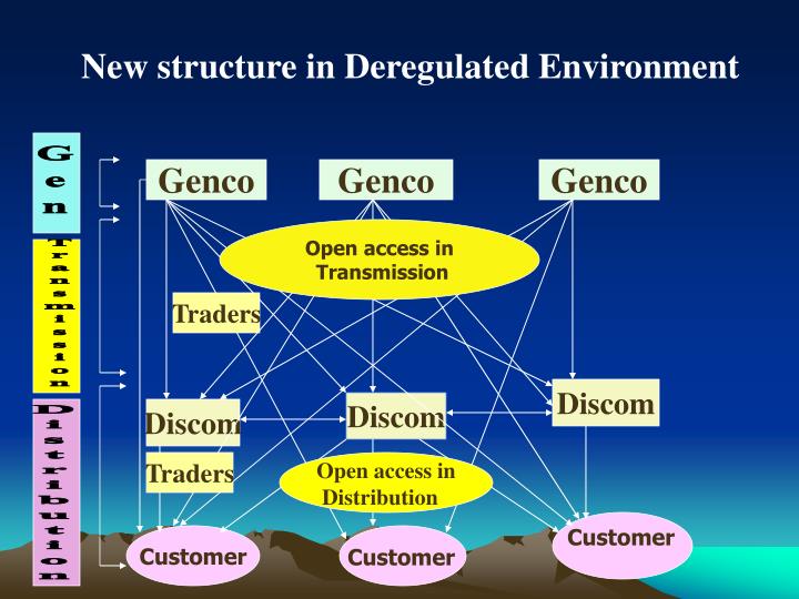
New structure in Deregulated Environment Genco Genco Genco Gen Open access in Transmission Traders Transmission Discom Discom Discom Traders Open access in Distribution Distribution Customer Customer Customer
These changes require the following: 1) Monitoring system wide information and commands via data communication system 2) To send selected local information to control center, customer, market participants. 3) Monitor critical real time information for taking security related operation . 4) To support Power Trading and spot market.
4) Reliable and fast communications among IED’s ( Intelligent Electronic Devices viz Relays, Meters, Fault recorders, RTU’s etc.) for exchanging information and change in settings as part of wide area protection system . 5) Dissemination of billing and other related calculations from Generation to Distribution for to various agencies including information for DMS & EMS. 7) To perform effective co-ordination through communications , Communication Protocols used are expected to be high speed ,reliable , fault tolerant and intelligent enabled.
8) The Protocols are to be accomplished for both local ( LAN) and wide area communications (WAN). 9) The protocols should be thin, flexible and have provisions for accommodating future requirements. 10) Safe , secured and reliable transmission of information. 11) Protecting information network from Hacking & misuse.
12. Information about the power system gives the utility the strength to be more successful and competitive in a free market . 13.In this environment information becomes a strategic requirement when fast decisions are required.
Remote Center HMI Hard Copy Printer Event Printer Ethernet LAN Engineering Tool ISAGRAPH ER1000 Station Controller Fault Analysis Reyevo / SEL5601 / IPSCOM Ohmega Argus Duobias-M SEL-311C M-3425 Multifunction Meter Delta Typical Substation Automation System Architecture
What is Protocol ? When Intelligent Devices communicate with each other, there needs to be a common set of rules and instructions that each device follows. A specific set of communication rules is called a protocol.
* The diversity of Equipments and Manufacturers lead to a increase of Proprietary Protocols
Computer to Computer data communication standards have been developed over past few decades. • Well known model for this purpose is the 7 Layer OSI ( Open System Interconnection) reference model.
This model provides encapsulation of the relevant data with in a packet. • This model provide isolation of application program from system and media. But adds significant overhead in processing power and bandwidth utilisation.
OSI 7 Layer Model Application 7 Presentation 6 Sessions 5 5 4 Transport Network 3 Data link 2 1 Physical
Functionality of different layers • Application Layer: This provides the interface and services that support user application. Ex. E-mail, WWW, SMTP. • Presentation Layer: This layer responsible for data encryption, data compression .Ex JPG, MPEG etc • Sessions Layer: Responsible for setting up the communication link and manages the sessions. It could provide connection oriented and connectionless services.
Functionality of different layers • Transportation Layer: Responsible for flow control, Packet size, error free delivery with proper sequence. • Network layer: Route determination takes place in this layer. Translation of IP address to physical address ( NIC) also takes place here. • Data link layer : Responsible for data movement across the actual physical link. • Physical Layer: It defines the physical aspect of how the cabling is hooked.
SystemX System Y 7 LAYER Application ••••••••••••••••••••••••••••••••••••••••••••••••••••••• 7 7 Presentation 6 6 ••••••••••••••••••••••••••••••••••••••••••••••••••••••• Peer communication Protocols ••••••••••••••••••••••••••••••••••••••••••••••••••••••• Session 5 5 ••••••••••••••••••••••••••••••••••••••••••••••••••••••• Transport 4 4 Intermediate System A Intermediate System B ••• ••• ••• 3 3 Network 3 3 2 2 2 ••• ••• 2 ••• Data Link 2 2 1 1 1 ••• ••• 1 ••• Physical 1 1 PhysicalMedia Physical Media Physical Media
Due to addition of many layer • overhead and bandwidth goes • higher. • It is not suitable for SCADA application. • Most of the Protocols follows various flavours of this model.
Need For Standards * Protocol is a set of rules that governs how message containing data and control information are assembled at a source for their transmission across the network and then dissembled when they reach their destination. * The communication protocol allows two devices to communicate with each other. Each device involved in the communication must essentially support not only the same protocol but also the same version of the protocol. Any differences involved in the implementation of protocol at the either of ends will result in the communication errors.
Proprietary Vs Open Protocols * Protocol, used by the vendor, the utility is restricted to one supplier for support and purchase of future devices. This presents a serious problem. Examples of Proprietary Protocols are SPA, K-Bus, VDEW etc. * With the arrival of open systems concept , it is desired that devices from one vendor be able to communicate with those of other vendors i.e. devices should inter-operate . To achieve interoperability one has to use industry standard open protocols. Ex: IEC60870 -5-103,101,104, IEC61850,DNP,Modbus etc
Advantages of Open Protocols * Migration to standard communication protocol is a very important decision that leads to cost reduction and maximized flexibility within the utility sector. Broadly benefits for the utilities are: Availability of open system connectivity > Vendor independence > Reliable products at optimized costs > Easily available knowledge and specification Benefits drawn for vendors by standardization are: > Lower costs of installation and maintenance > A large market and thus opportunity to compete on price performance instead of technical details only. > Cost effective project implementation
Interoperability Vs Interchangeability * Interoperability is the ability of two or more IEDs from same vendor or different vendors to exchange information and uses that information for correct co-operation. * Interchangeability is the ability to replace the device the supplied by one manufacturer with a device without making change to the other elements in the system.
Application Application Session Presentation Transport Network Data Link Data Link Physical Physical PROTOCOL STRUCTURE 7-Layer 3-Layer EPA OSI
Application Presentation Session Transport Network Data Link Physical Network Technology mainly based on OSI (Open System Interconnect) which is a 7 Layer model representing networking node by dividing tasks into layers that perform specific Functions. Logical Connection Application Application Presentation Presentation Session Session Transport Transport Network Network Data Link Data Link Physical Physical Physical Connection OSI Seven Layer architecture
Application Presentation Session Transport Network Data Link Physical PROTOCOL STRUCTURE for IP based Open Protocols IEC, DNP, UCA (and even MODBUS) standards are successfully able to adopt TCP/IP based Ethernet based technology for substation automation. IEC 61850 (UCA2) IEC 104 DNP3/TCP } TCP/UDP TCP/IP IP } IEEE 802.1 Ethernet IEEE 802.3
Link LayerBalanced Transmission Request Message Slave Master (User Data, Confirm Expected) [P] (Acknowledgment) [S] Response Message (User Data, Confirm Expected) [P] (Acknowledgment) [S] [P] = Primary Frame [S] = Secondary Frame
Link LayerBalanced Transmission • At the link layer, all devices are equal • Collision avoidance by one of the following: • Full duplex point to point connection (RS232 or four wire RS485) • Designated master polls rest of slaves on network (two wire RS485 and disable data link confirms in slaves) • Physical layer (CSMA/CD)
Link LayerUnbalanced Transmission Request Message Slave Master (User Data, Confirm Expected) [P] (Acknowledgment) [S] Response Message (Request User Data) [P] (Respond User Data or NACK) [S] [P] = Primary Frame [S] = Secondary Frame
Link LayerUnbalanced Transmission • Only Master device can transmit primary frames • Collision avoidance is not necessary since slave device cannot initiate exchange, or retry failed messages • If the slave device responds with NACK: requested data not availablethe master will try again until it gets data, or a response time-out occurs
Protocols used in Electrical utilities are as follows: • Modbus / Profibus • DNP ( Distributed Network Protocol ) • IEC 60870 series • UCA ( Utlity Communication Architecture ) – IEC 61850 series
MODBUS • Developed in the process-control industries by MODICON , USA during 1976 • - Application layer Protocol ( 7 th Layer of OSI ) • Extensively used in industrial environment • Used in process bus of substation bay ( Relays ) • It operates on master slave type mode • Slave node will not typically transmit data with out a request from the master.
It was originally designed as a simple way to transfer data between controls and sensors via RS-232 interfaces. • Modbus now supports other communication media, including TCP/IP. • Modbus is now an open standard, administered by the Modbus-IDA (www.modbus-ida.com).
Modbus and DNP are both byte-oriented protocols. Modbus is an application layer protocol, while DNP contains Application and Data Link Layers, with a pseudo-transport layer. Both protocols are widely used over a variety of physical layers, including RS-232, RS-422, RS-485, and TCP/IP. Modbus has a separate specification for use over TCP/IP (Modbus-TCP). With DNP, the protocol is simply encapsulated within TCP/IP. Modbus and DNP3 Communication Protocols
Distributed Network Protocol ( DNP) was developed by Harris, USA. • The Distributed Networking Protocol (DNP) was originally developed by Westronic, Inc. (now GE Harris) in 1990. • The “DNP 3.0 Basic 4” protocol specification document set was released into the public domain in 1993, and ownership of the protocol was given to the newly formed DNP Users Group in October 1993. • DNP was specifically developed for use in Electrical Utility SCADA Applications. • It is now the dominant protocol in electrical utility SCADA systems, and is gaining popularity in other industries, including Oil & Gas, Water, and Waste Water.
In 1993 the responsibility for defining further DNP specification was given to DNP user Group. • DNP is based on the earlier work of IEC TC 57 • It is based on Enhanced Performance architecture ( EPA) model • There are 4 core documents to define DNP 3
Emergence of Standard • DNP 3.0 • Based on earlier work of IEC TC57 • Developed by GE Harris DNP 3.0 is an open protocol that was developed to establish interoperability between RTUs, IEDs (Intelligent Electronic Devices) and master stations. DNP was largely influenced by North and South America, together with the African and Asian regions as IEC 101 was from the European community.
DNP 3.0 Structure • Three Layered Protocol (EPA) • Application (Layer 7) • Data Link (Layer 2) • Physical (Layer 1) This structure is similar to IEC. However, DNP3 enhances EPA by adding a fourth layer, a pseudo transport layer that allows for message segmentation.
Additional Pseudo Layer • In addition • Pseudo Transport Layer (Layer 4) • Support Advance RTU functions DNP introduces a pseudo-transport layer(OSI Layer 4) to build application data messages larger than a single data link frame. In case of IEC, each 101 message should be contained in a single data link frame.
DNP3 is an open, intelligent, robust, and efficient modern SCADA protocol. • It can request and respond with multiple data types in single messages, • segment messages into multiple frames to ensure excellent error detection and recovery, • include only changed data in response messages, • assign priorities to data items and request data items periodically based on their priority, • respond without request (unsolicited), • support time synchronization and a standard time format, • allow multiple masters and peer-to-peer operations, • and allow user definable objects including file transfer. • In 1994, the IEEE Power Engineering Society’s Data Acquisition, Monitoring and Control Subcommittee formed a Task Force to review the communication protocols being used between Intelligent Electronic Devices (IEDs) and Remote Terminal Units (RTUs) in substations.
The IEEE Task Force found a very confusing, constantly changing environment that was increasing the cost and time to completion of substation SCADA systems. • The IEEE Task Force collected information on approximately 140 protocols and compared them to a list of communication protocol requirements. • This comparison resulted in a short list of protocols that met most of the requirements. • This short list was balloted and two serial SCADA protocols tied for being the most acceptable: IEC 60870-5-101 and DNP3.
Structure of IEC 60870-5 • Three Layered Protocol(EPA) • Application (Layer 7) • Data Link (Layer 2) • Physical (Layer 1)
For Tele Control System that require particularly • Why 3-Layered Structure of EPA 1) Short Reaction Time 2) Reduced Transmission Bandwidth BW:Measure of capacity of a transmission system. Measured in Hertz. How fast data can flow on a given transmission path. In Digital data transmission, BW is expressed as data speed in bits per second. Thus, higher the BW, more data can be transmitted.
Purpose of 60870-5 Protocol • High Integrity • Efficient Data Transmission • Protection Against Undetected TransmissionErrors Correct data should reach the destination Without Loss
DNP 3.0 and IEC 60870-5-101 • Both DNP 3.0 and IEC 60870-5-101 • Designed for Transmission of SCADA Data for Electric Power System Control • Wide Market Acceptance • Intended for Use in SCADA Systems Using directly Connected Serial Links
DNP 3.0 and IEC 60870-5-101 • 60870-5-101 and DNP Usage • Collection of Binary Data • Collection of Analog Data • Collection, freezing and Clearing of Counters
DNP 3.0 and IEC 60870-5-101 • Time Synchronization • Time-Stamping Events • File Transfer • Unsolicited Events Reporting
IEC 60870-5 Series It is bit serial communication standards. The standard is optimised for efficient and reliable transfer of process data and commands to and from geographically widespread systems over low-speed (up to 64 kbps) fixed and dial-up connections.
IEC 60870-5-101 – It deals the functionality for the interoperability of telecontrol equipment of different manufactures for the communication between substations and between substation and control centres . IEC 60870-5-102 - This standard deals with values of integrated totals which are transmitted at periodic intervals to update the energy interchanges between utilities or between heavy industry and utilities.
IEC 60870-5-103 - This deals with informative interface of protection equipment . IEC 60870-5-104 - This present a combination of the application layer of IEC 60870-5-101 and the transport functions provided by a TCP/IP.
IEC 61850 This standard unifies UCA with European standard. It aims to design a communication system that provides interoperability between the functions to be performed in a substation.
IEC 61107 : This specifies hardware and protocol specifications for local systems in which a hand held unit is connected to only one tariff device at a time. This specifies hardware and protocol specifications for local systems in which a hand held unit is connected to only one tariff device at a time.
·1)IEC 61107 is essentially a protocol providing a means to access (read and write) memory locations, without telling anything about how those memory locations should be filled with information. · 2) IEC 61107 does neither say anything about the format and the interpretation of the data.