Download
1 / 65
650 likes | 905 Vues
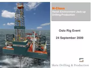
N-Class Harsh Environment Jack-up Drilling/Production. SKDP N-Class Jack-Up Unit Drilling/Production. Company Background Rig Concept and Design Operations Management QHSE. SKDP CLASS-N JACK-UP UNIT TABLE OF CONTENT. 1. 2. 3. 4.

E N D
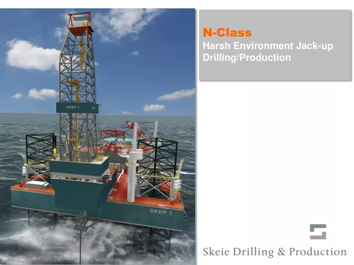
N-Class Harsh Environment Jack-up Drilling/Production SKDP N-Class Jack-Up Unit Drilling/Production
Company Background Rig Concept and Design Operations Management QHSE SKDP CLASS-N JACK-UP UNIT TABLE OF CONTENT 1 2 3 4
COMPANY BACKGROUND COMPANY INTRODUCTION – SKEIE DRILLING & PRODUCTION • SKDP established September 2006 and located in Kristiansand, Norway. • 31% owned by Skeie Technology AS, 12% by Wideluck Enterprises and 57% by external investors (Post financial restructuring in July 2009). • Signed contract for design and construction of three KFELS Class N Jack-up Unit with delivery in 3Q and 4Q 2010, and 2Q 2011. • OTC listed in Oslo. • Operational Management: Skeie Rig Management.
COMPANY BACKGROUND KEY COMPANY STRUCTURE Skeie Drilling & Production ASA (Kristiansand, Norway) SKDP Project Management/Project Supervision Group (Kristiansand, Norway; KFELS Shipyard, Singapore; Sub-Contractor Manufacturer Yards) Skeie Rig Management Group (Onshore) (Trondheim, Norway + Local Base Office) KFELS Shipyard Singapore (Engineering / Construction) Rig Offshore Organisation Sub-Contractor Manufacturer Yards (Engineering / Construction)
Oil Company Skeie Drilling & Production MARKETING & SALES SKDP OPERATION Tomas Norrby Stein Eggan Willy Tørhaug Dag Eggan SKDP PROJECT TEAM Tom Mikkelsen HSE ADVISOR QA/HSE TECHNICAL MANAGER Dag Eggan Jan Brataas Helge Skeie PURCHASE DOC.CONTR./SEC. Jens Ugland Beate Austefjord HULL MACHINERY El./INSTR. DRILLING SITE TEAM PRODUCTION FSO Arnt Henriksen Stein Anderssen Halvor Flatland Trond Standal STRUCTURE JACKING SYSTEM POWER SYSTEM DRILLING EQUIP SITE MANAGER Vetco Aibel AS OSM Offshore AS Arne Tønnessen Morgan Tønnessen Halvor Flatland Yngve Kristiansen Mark Aitken MARINE/ACCOM. MACH.SYSTEMS COMMUN. / INSTR. MUD SYSTEM Arnt Henriksen Stein Anderssen Keesoon Woon Knut Bakke PIPING TBN COMPANY BACKGROUND SKDP – PROJECT ORGANISATION
COMPANY BACKGROUND PROJECT INTERFACE – RESPONSIBILITY AND MANDATE • OPERATIONS GROUP • Prepare Operational Documentation • Prepare Maintenance Procedures • Prepare Acceptance Criteria • Assist Project and Verify Operability • System by system • Area by area • Accept and Operate • Coastal Authority Certification (PSA) • Client Interface • PROJECT GROUP • Supervise the engineering, construction, documentation and delivery of the Rig: • Fully commissioned • Documented • Certified (Flag State and Class) • Ready for Operations FORMAL HANDOVER DELIVERY ACCEPTANCE
Company Background Rig Concept and Design Operations Management QHSE SKDP CLASS-N JACK-UP UNIT TABLE OF CONTENT 1 2 3 4
Self-Elevating Drilling Unit (KFELS Class N) Harsh Environment North Sea and Canadian waters High pressure/high temperature deep well GoM Extended reach and transverse skidding of Drill Floor Combined drilling & production facilities 10 wells tie back or sub sea completion with production module installed Subsea well completion with HP riser and dry BOP over large subsea template – 75 ft long x 66 ft wide Large Subsea X-mas tree (45 mt) handling through Cantilever hatch 5x6m Operations in 122 meters water depths. Optional 131 meters with 30 ft. leg extension. Drilling depth up to 35,000ft (10,667M) Set Back. Derrick 1100 tons. Triangular hull with three (3) triangular truss legs each fitted with a spud can with tip at its lower end. The triangular hull is 264 ft. (80.46M) long, 289 ft. (88.09M) wide, and 35 ft. (10.67M) deep at the side. LQ designed to accommodate 120 persons. Helicopter deck designed for Sikorsky 61N and S92 helicopter. RIG CONCEPT AND DESIGN SPECIFICATIONS FOR DRILLING AND PRODUCTION OPERATIONS
RIG CONCEPT AND DESIGN CONSTRUCTION WORK KEPPEL FELS, SINGAPORE
RIG CONCEPT AND DESIGN COMBINED DRILLING AND PRODUCTION OPERATIONS Limits Area: 12,918 sq ft (1,200M2) Height: 52.5ft (16M) The Cantilever and Drill Floor can be repositioned 26ft (7.92M) to the Port side of the Vessel, to allow space for installation of a future production process module.
RIG CONCEPT AND DESIGN COMBINED DRILLING / PRODUCTION UNIT WITH STORAGE TANK
Drill Floor located on the substructure above the cantilever. Cantilever capable of being skidded fore and aft with center line (primary Cantilever position) of rotary up to 75 ft (22.86m) aft of sternIt can be relocated 26 (7,92m) ft to port (secondary Cantilever position) The Drill Floor can be skidded 20 ft (6.1m) port and starboard of the Cantilever centerline both in primary position and in secondary position Max operation envelop over a pre-installed Jacket/Wellhead Platform:75 ft aft of Transom, 20 ft to starboard of hull centerline and 46 ft to port of hull centerline. RIG CONCEPT AND DESIGN SPECIFICATIONS FOR DRILLING AND PRODUCTION OPERATIONS
The Cantilever and Drill Floor can be repositioned 26ft (7.92M) to the Port side of the Vessel, to allow space for installation of a future Production Process Module. 12,918ft2 (1,200m2) in area and 52.5ft (16m) maximum in height. With the cantilever/drill floor in offset position with 10 wells tie back (1500 ton tension) Row no. 1 - 5 wells 12 ft aft of transom Row no. 2 - 5 wells 20 ft aft of transom With cantilever in secondary position and no production module installed a total of 12,918 square ft (1200 square m) free main deck area is available in one common space. (Page 16) RIG CONCEPT AND DESIGN SPECIFICATIONS FOR DRILLING AND PRODUCTION OPERATIONS
RIG CONCEPT AND DESIGN DESIGN OPERATING CONDITIONS – STANDARD DRILLING MODE Design Operating Conditions Design Storm Survival Conditions
RIG CONCEPT AND DESIGN TECHNICAL COMPARISON WITH PEERS 1) Enhanced version of the existing CJ-70 design with increased drilling depth, increased variable deck load and 1000 t top drive. Source: Company, ODS Petrodata
RIG CONCEPT AND DESIGN TECHNICAL COMPARISON OUTSIDE NORTH SEA (1) Depending on actual location criteria and leg extensions
RIG CONCEPT AND DESIGN OPTIMISED DRILLING EQUIPMENT • Derrick model SSBN 1100-40X40X180 • Crown block/Traveling block 1100 sh. Tons 72” diameter 2” groves. • Top Drive Model HPS 1000-2E-AC-KT Torque 78450 ft. Lbs. continious • Retractable Dolly for Top Drive • Drawworks 1100 sh. Ton 16 lines 4XAC GE motors with regenerative braking + disc brakes for parking and emergency brake • 1000 sh Ton Rotary support table 49 ½”, Max 15 rpm / 45000 ft.Lbs. at 5 rpm.
RIG CONCEPT AND DESIGN OPTIMISED DRILLING EQUIPMENT • Dead line anchor 160 kip. Floor mounted Rotary slip • Dual Hydraulic catheads with commen control panel • Pipe Racker 10 ton lifting capacity. Parallel racking of 90 ft stand. Off line Stand building capability for DP, DC and Casing. • Fingerboard: 35.000 ft racking capacity. DP- 273 st. of 5 7/8” and 108 st. of 6 5/8”, 10 st. of 9 ½” DC, 22 st. of Casing 9 5/8” or 14 st. of Casing 13 3/8” • Belly Board for 190 stands locking latch for each pipe slot. • Stabbing basket/work basket 250kg swl.
RIG CONCEPT AND DESIGN OPTIMISED DRILLING EQUIPMENT • Drillers Cabin elevated 2 m with 2 chairs and Cyberbase operation stations. • Catwalk machine with remote control from DCR or Drill floor and tail in /out arm for transport of DP, DC and Casing up to 36” OD to rotary, separate pull back winch on Catwalk structure • Drill floor Manipulator Arm with remote control from DCR or Drill floor for DF handling and tail in operations of large tubular • Pipe handling crane Working radius 25 m. SWL 5.5 Mt. • 3 x 5t utility winches with remote control, installed in Derrick level at level 4 • 1 x Derrick Man rider winch with remote control, installed in Derrick level at level 4 • Iron Roughneck type Wellquip (JIM)
RIG CONCEPT AND DESIGN WELL CONTROL EQUIPMENT • Surface 18 ¾” BOP Shaffer 18-15M - 1ea spherical 10 K - 1ea pipe Ram 15 K - 1ea. Shear Ram 15 K with Booster for max shearing capacity - 2ea. Pipe Ram 15 K - 2ea.3 1/16” 15 M type DB valve Hydraulic operated - 2ea 3” 15 M type B valve manually operated • Koomy Hydraulic Power Unit - Remote control of HPU functions from Drillers panel and Tool Pushers panel - Emergency remote operating panel located in central control room - 3000 psi. working pressure - Accumulator capacity to meet API 16D and PSA requirements
RIG CONCEPT AND DESIGN WELL CONTROL EQUIPMENT • Choke & Kill Manifold 15 K - 2ea Remote operated chokes from Drillers Cabin - 2ea. Manual operated choke • 1ea. Poor boy degasser 12” went line to top of derrick and 20’’ U-tube • 2ea. Swaco CD 1400 degasser with blower • Vetco KFDJ-500 Diverter System • Equipped with 20’ “U-Tube” for HPHT NORSOK D-001
RIG CONCEPT AND DESIGN EQUIPMENT IN CANTILEVER • BOP Overhead Crane with 2x75 T SWL The two hoist beams are split to operate 75 T of each side of the well centre. For lifting of the BOP or sub sea X-mas Tree, the 2 hoists beams run simultaneously. • 2 x120 t BOP skid to handle BOP or X-Mas tree from landing area to BOP Crane working area, or onto BOP 130 t trolley • 1 x Cellar deck opening 130 t BOP trolley with 60 ½” opening through • 1 x Cellar deck transverse moving and telescopic work basket • 1 x Cellar deck Man rider winch with remote control, installed in cantilever • 2 x 5 t utility winches with remote control in Cellar deck • Conductor Tensioning System 318 MT capacity fold down conductor tensioning platform (centre 20 feet aft of hull) • Riser Tensioning System 318 MT capacity – 4 cylinders installed below Drill floor • BOP tensioning system 140 MT capacity – 4 cylinders installed below Drill floor
RIG CONCEPT AND DESIGN MUD CIRCULATING SYSTEM • 3 x Mud HP pumps 7500 psi. Model NO 14-P-120. 2200 HP/2 GE AC motors and Centrifugal pumps arranged for charging. • 5 x VSM 300 dual deck Shale Shakers. • 2 x centrifugal mixing pumps arranged with manifold for simultaneous mixing in active pits and reserve pits • Power and piping provided to delegated place for Centrifuge.
RIG CONCEPT AND DESIGN BULK TANKS (P TANKS) • Five (5) mud tanks each of 1875 cu ft (50 m3) and four (4) cement tanks each of 1875 cu ft, (50 m3). • Operating pressure of 60 psi and bulk material specific gravity 2.163. • Mud additive system with skid mounted sack cutting unit, big bag unit, liquid additive skid, high rate mixer, HP mud share unit, density control unit and caustic mixing unit.
RIG CONCEPT AND DESIGN TANK CAPACITY Tank Capacity:Total capacity Fuel oil (3 tanks) 880 m3 Base oil tank 330 m3 Brine oil (2 tanks) 782 m3 Mud pit 1050 m3 Mud contaminated tank 10 m3 Drillwater (2+8 tanks) 6094 m3 Fresh water (2 tanks) 831 m3
RIG CONCEPT AND DESIGN DECK LOAD PLAN • Canteliver Pipe Rack (800 kips) 363 ton 2637 kg/m2 • Total setback area (1200 kips) 544 ton • Drillfloor working area 1953 kg/m2 • Drawworks house top 459 kg/m2 • Main deck (outside pipe rack) 2075 kg/m2 • Pipe rack (Main Deck) 2637 kg/m2 • IWO Production module 3330 kg/m2 • Quarters deck & plan 459 kg/m2 • Loading platform 1318 kg/m2 • Emergency Generator room 459 kg/m2 • Helideck is designed for Sikorsky S61 and S92 Helicopters in accordance with CAP 437
RIG CONCEPT AND DESIGN RIG CRANES • 1 ea. Electro hydraulic driven Deck crane starboard aft.Certified for Zone 1, compliance with PSA/NMD regulation. SWL 50 Mt @ 36 m SWL 38,1 Mt. @ 46m • 2 ea. Diesel engines driven Deck cranes port side and starboardCompliance with PSA/NMD regulations.1 off SWL 50 Mt @ 36 m / SWL 38,1 Mt @ 46m1 off SWL 50 Mt @ 20 m / SWL 14,5 Mt @ 46m
RIG CONCEPT AND DESIGN WELL TESTING PROVISIONS AND AREAS • Well Testing Area assigned starboard aft between aft leg and cantilever (area approx 7,5 x 9,0 meters) • Two burner booms will be installed on each side • Piping System • 1 off 4" line, 10.000psi (1700 bar), HP line from DF to well test area • 1 off 6” line, 1500 psi (260 bar), gas line from well test to each burner boom • 1 off 4” line, 1500 psi (260 bar), oil line from well test to each burner boom • 1 off 4” line, cooling water line to each burner boom • 1 off rig air line each burner boom
RIG CONCEPT AND DESIGN PROCESS MODULE FACILITATION - KEY ARRANGEMENTS DONE • Space provision on main deck for Production Process and Utility Module • Fire Water/Deluge System interface to future Process Module;To provide sufficient fire water and deluge capacity for both rig and process module systems, the following arrangements is provided for: • Rig fire ring main to accommodate the full fire water flow based on total required flow rate of 1800 m3/h • Provide additional guides on legs for three future raw water pumps based on two guide pipes per leg. • Accommodate space for addition self contained future fire water "containers" that also has a generator included to drive the dedicated raw water/seawell pumps for each fire pump unit. There will be space for 3 containers each drawing from a separate leg and tying into the firewater ring main. • Connection points in the fire water ring main for supply and off take of firewater • Space for future piping to fire water pump containers • Structural strength; The hull reinforcements are based on a weight of Production Process and Utility Module of maximum wet weight of 3,500 MT. The Weight of the Utility Module of 1500 MT and Process Module of 2000 MT were used to define the supports. If there are any changes of the Production Module weights, distribution and the Support foot print position, a re-assessment of the hull support interface will be required. • Cooling water supply to production plant; Guides provided for the three additional future raw water pumps for cooling water based on two guide pipes per leg. A seawater cooling line of 20” is installed and based on 2000m3/hr flow rate.
RIG CONCEPT AND DESIGN KEY ARRANGEMENTS DONE • Rig strengthening for Wellhead Platform for the Production Risers;The hull is designed to support the risers and wellhead platform at the transom. The wellhead platform connection to the transom will be provided at four locations vertically on both sides of the wellhead platform in way of the eight connections. Pin connections are assumed Reinforcement is based on 1500 tonnes Risers load and 300 tonnes Wellhead self-weight. • Arrangements for Drilling Rig ESD system to communicate with the Process Module ESD system;Rig ESD comes with provision to transfer 20 signals via hard wire to Process ESD systems including cabling work. ESD panel is be expandable. • Control Room Integration for Process Module;Four (4) cable tray of 600mm width, 200m length is catered for instrument cables coming from the process plant to the Central Control Room. • Space/facility arrangements for Emergency Switchboard Power for Production Unit (e.g. lighting etc.) based on PROD (N) Requirements;A 100kW Power feeder from Emergency Switchboard for Process Module is provided. • Compressed Air/Instrument Air supply to Production Module area using existing rig air system/compressors; One 3” service outlet with shut off valve is provided for next to the future Process Module. • Communications System – PA/GA;Rig PA/GA is provided with following speakers, telephones and stations. • PA/GA Speakers ea 10 • Telephones ea 6 • General Alarm Stations ea 10
RIG CONCEPT AND DESIGN KEY ARRANGEMENTS DONE • Fuel oil supply to process area;A 2” service outlet with shut off valve is provided next to the future Process Module. • Arrangement for service utilities in process area – 230 V / 480V;3 X 230 V outlets and 3 X 480V outlets taken off from the nearest power panel next to the future Process Module are provided. • Arrangements for Fresh/Sea Water supply to process area;2” FW & SW service outlet with shut off valve are provided next to the future Process Module. • Starboard aft crane is certified for use in Hazardous Area Zone 1 (i.e. over and next to the future Process Module).
RIG CONCEPT AND DESIGN DESIGN BASIS • The process system is generic designed for two types of concepts: • Oil fields which require a one stage separation of liquid and gas before export to an existing oil processing plant. • Oil fields which require a two stage separation to stabilize the oil for export to an oil tanker. • The topside process facility is divided into different module areas: Process Module: • Production Manifold • Oil Separation • Gas Compression • Water Injection • Produced Water Treatment • Chemical Injection • Fuel Gas System • Seawater Filtration Utility Module: • Power Generation • Heating Medium • Nitrogen Generation • Flare KO / Closed Drain Drum Skid • Flare/Closed Drain System • Flare Tower
RIG CONCEPT AND DESIGN BASIC PROCESS CAPACITIES N-Class facility 1) Subject field specific evaluation
RIG CONCEPT AND DESIGN OIL STORAGE AND EXPORT SOLUTIONS • Subsea storage tank (steel / concrete) • FSO • Offloading to shuttle tanker
Company Background Rig Concept and Design Operations Management QHSE SKDP CLASS-N JACK-UP UNIT TABLE OF CONTENT 1 2 3 4
OPERATIONS MANAGEMENTOPERATIONS MANAGEMENT STRUCTURE • Skeie Rig Management AS (SRM) established in Trondheim in 2008 as a wholly owned SKDP subsidiary. • SRM will be responsible for all rig operations after delivery from yard. • Key onshore and offshore management positions and section leaders already recruited. • Pre-operations activities ongoing • Training and competency development programs under development • QHSE management systems established. • Maintenance systems. • Logistics (spare parts)
OPERATIONS MANAGEMENT SKEIE RIG MANAGEMENT – RECRUITMENT AS PER SEPTEMBER 2009 SKEIE DRILLING & PRODUCTIONCEO/PresidentTomas Norrby OWNER / CONTRACT HOLDER SKEIE RIG MANAGEMENTManaging DirectorStein Eggan OPERATIONS MANAGEMENT COMPANY * This function may support several units depending on the area of Operations as reflected in Base Organisation structure. Human Resources ManagerGeir Bjørsvik Office Administration ManagerRandi Damstuen Finance/Accounting ManagerHeidi Fornes IT SupportFrank Ådnevik (Enitro) Business Dev./ MarketingStein Eggan Chief Operating OfficerWilly Tørhaug QHSE DirectorDag Eggan Operations Manager(SKDP Units) Administration/Doc. Control Randi Damstuen Supply/Purchasing ManagerStephen Knight Accounting/Payroll Manager*Ann-Karin-Dullum Personnel Co-ordinator *Kirsti Jenssen QHSE Manager TBD Technical Support Manager TBD OPERATIONS BASE ORGANISATION Maintenance ManagerTerje Lindrupsen SKDP Rig No. 3Rig Manager Håvard Skagen SKDP Rig No. 2Rig ManagerTBN SKDP Rig No. 1Rig ManagerOdd Magnar Johnsen E&I ManagerBjørn Lilleeide Org. Structure as for Rig No. 1 Org. Structure as for Rig No. 1 Ass. Rig Manager(PENDING CONTRACT) Drilling ManagerTBD Technical SuperintendentPer Revheim QHSE AdvisorTBD Marine ManagerTBD Technical Limit Co-ordinator(PENDING CONTRACT) Supply/PurchasingJohn Larsen Drilling Eq. SpecialistKristian Skagemo Personal Co-ordinator * TBD Process Manager(As Applicable) Rig Accountant *TBD Rig Offshore OrganisationOIM
OPERATIONS MANAGEMENT UNIT OFFSHORE ORGANISATION – AS PER JAN 2009 Permanent Crew Onboard - # 25 Drilling Mode Crew – # 14 Offshore Installation Manager (OIM)Atle Fjørtoft (01.02.09)Rasmus B. Larsen (01.12.08) Production Mode Crew - # 7 Pending Activity Crew – # 6 Admin. Camp Boss Total Crew No. Drilling/Production Mode - # 52 Medic Safety Officer Rig Operations SuperintendentPeder AndreasenKjell Arne Orvik (01.02.09) 1+(1) x Storekeeper* ProcessSection Leader Stability Section Leader Technical Section LeaderBjørn Glørstad (01.01.09)HenrikBirnbaum (01.12.08) Drilling Sect. Leader (Toolpusher)Kim V. Sørensen (01.12.08) Stability S.L. II 2 x Process CCR Op. TourpusherAlaln Hay (01.12.08)Ole Villefrance (01.12.08) Lead E & I Engineer Ass. Tech. Sect. Leader 4 x Process Operator Electrician Engine Room Op. 2 x Crane Operator 1+(1) x Driller* Electrician Motorman 2 x Ass. Crane Operator 2 x Assistant Driller 2+(2) x Roustabouts* Hydraulic Engineer 2 x Derrickman Rig Mechanic 2 x Pumpman Welder 6 x Roughneck * Number in brackets (#) indicates additional number for full Drilling or combined Drilling/Production mode activity.
Company Background Rig Concept and Design Operations Management QHSE SKDP CLASS-N JACK-UP UNIT TABLE OF CONTENT 1 2 3 4
QHSE MANAGEMENT SYSTEM FRAMEWORK QHSE MANAGEMENT SYSTEM OVERVIEW
QHSE MANAGEMENT SYSTEM FRAMEWORK INTEGRATED QHSE MANAGEMET SYSTEM MODEL QHSE Management System Key Management System Elements
QHSE MANAGEMENT SYSTEM FRAMEWORK SUPPORTING CONTROLLING DOCUMENTATION Unit Specific Level 1) Corporate & Area Base Level CONTRACT SPECIFIC QUALITY PLANS(OR BRIDGING DOCUMENT) CORPORATE VISIONS AND POLICIES OPERATION MANUALS FOR THE UNIT(REF. SEPARATE SLIDE) COMPANY STANDARDS EMERGENCY PREPAREDNESS MANUAL ONSHORE CONTINGENCY MANUAL(3rd Line Strategic Management) SOPEP MANUAL QHSE MANAGEMENT SYSTEM MANUAL SHIP SECURITY PLAN QHSE MANAGEMENT PROCEDURES MANUAL RIG MOVE MANUAL MAINTENANCE MANAGEMENT MANUAL UNIT SAFETY BOOKLET COMPANY CORPORATE FORMS POTABLE WATER MANUAL PERSONNEL HANDBOOK UNIT TECHNICAL SPECIFICATION OCCUPATIONAL HEALTH & SAFETY SERVICESMANUAL YEARLY HES PROGRAM FOR THE UNIT Above Corporate Documentation will also apply for local Company Entities including Branch- and Base Offices with local adjustments as required in the QHSE Management Procedures Manual and Onshore Contingency Manual. COASTAL STATE REGULATORY CERTIFICATIONAoC / UK Safety Case / CoF / US CG LoI (including Key Risk / Working Environment Analysis) • Unit specific “as built” documentation, including P&ID’s, drawings, design philosophies, vendor documentation etc., is not included in the listing of Unit Specific Documentation. • Reference is also made to procedureSKDP-QHSE-PRO-001.