Download
1 / 28
310 likes | 667 Vues
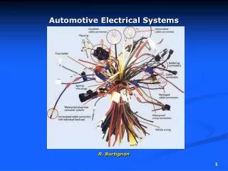
Power Interface for New 42V Automotive Electrical Systems . ECE 345 Fall 2002 Blake Whetstone Audrey Klett Kwassy Surheyao. Background. The electrical system in automobiles is being updated from the standard 12 V power supply to the new 42 V battery.

E N D
Power Interface for New 42V Automotive Electrical Systems ECE 345 Fall 2002 Blake Whetstone Audrey Klett Kwassy Surheyao
Background The electrical system in automobiles is being updated from the standard 12 V power supply to the new 42 V battery. However, many older parts will follow that transition very slowly, and still hold old electrical system ratings.
Objective The objective of this project is to design and build an efficient and inexpensive power 42 V to 12 V DC-DC electronic converter to serve older parts of automotive electrical systems.
Benefits to Customer • Eases transition to new system without having to replace components • Inexpensive • Delivers more power to components • Allows time for transition to 42 V rated components
Design Considerations • Product Features: • Voltage Input Range: 30 V to 60 V dc • Voltage Output Range: 12V to 14 V dc • Maximum output power of 120 Watts • Input Logic Control Capability • Efficiency > 85% • Total Cost < $10
Design Considerations (cont) • Block Diagram Source Gate Drive Converter Voltage Regulator PWM Load Feedback
Buck converter • Schematic and basic operation • Initial calculations and analysis • Pspice simulations • Hardware build-up • Operating results
Buck converterBasic operation(1) Switch #1 ON, switch #2 OFF
Buck converterBasic operation(2) Switch #1 OFF, switch #2 ON
Initialcalculations • Lossless system condition: Pout = Pin • While the diode is ON, 12V ≤ Vout≤ 14V Iout1 = (120W)/(12V) = 10A Iout2 = (120W)/(14V) = 8.57A • Vout = 13V ± 1V ripple • Pout = 120 W • R = Vout2 / Pout = (13V)2/(120W) = 1.408 Ω • D1: Duty cycle of switch #1 (MOSFET) D2: Duty cycle of switch #2 (diode) D1 + D2 = 1 Vout = D1Vin • D1 = Vout / Vin → (12V)/(60V) ≤ D1 ≤ (14V/30V) 0.20 ≤ D1 ≤ 0.47 • D2 = 1 – D1 → 0.53 ≤ D2 ≤ 0.8 ∆i = 1.43A
Initial calculations • Choosing an inductance L Assumption: L > LCRIT → iL > 0 for Continuous mode operation • When switch #1 is ON: VL = LCRIT*di/dt • LCRIT = ((60V –12V)*D1MAX*T)/20 • LCRIT = (48V*0.47*20μs)/20 = 22.56μH • So we need to choose an inductor such that L > 22.56μH • When the diode is ON: ∆t = D2T, T = (50KHz)-1 = 20μs L = VL D2MAXT / ∆i = (13V)(0.8)(20μs)/(1.43A) L = 145μH We choose L = 100μH and a capacitor to control ripple.
Initial calculations • Choosing a capacitor C VC = 13V * 2% = 0.26V VC = i*D2T / (8*C) , i = (13V)*D2T/L VC = (13V)*(D2T)2 / (8*L*C) C (13V)*(D2MAXT)2 / (8*L*VC ) C 16μF We choose C = 20μF
Hardware Buildup • Gate Drive • Feedback control • Voltage Regulator
Gate Drive • Switching command for MOSFET gate • Vgs > 10V to turn on • -1V < Vs < 59V • PWM signal referenced to ground • High Side Drive references a 0 to 10V pulse signal from PWM to Source Voltage • HSD enables Vg to be 10V greater than Vs
Feedback Control • Controls Duty Cycle based on Vout • Signals used: • Voltage divider across Vout • Vref provided by PWM ~5V • Oscillator (Sawtooth waveform from PWM) • IC’s used: • UC3526 (PWM), MC33071 (op-amp)
Feedback Control Operation • Vref (5V) compared to Vout (scaled with voltage divider) in op-amp • Error (difference in Vref and Vout) multiplied by gain of op-amp (~10) • Op-amp output compared to oscillator • Square pulse waveform produced from comparison • Duty cycle determined by the amount of time the signal is high
Operating Performance Efficiency vs Vin with a 5.6 Ohms Load 100 90 With Independent Voltage Source 80 70 With Voltage Regulator 60 Efficiency (%) 50 40 30 20 10 0 30 35 40 45 50 55 60 Vin (V)
Operating Performance • Efficiency less than expected • Voltage Regulator draws current • 9V < Vout < 16V • Need better feedback control for duty cycle • Duty Cycle did not change as expected • Feedback control circuitry • PWM op-amp did not function properly • Current Ripple more than expected • Poor choice of testing instrument
Improvements • Feedback Control needs modified • Resistor/Capacitor Values • PWM’s reference voltage changed • Soft-Start instead of voltage regulator for powering IC’s • Synchronous Buck Converter Application