Download

1 / 17
170 likes | 288 Vues
Survey of Existing Memory Devices. Renee Gayle M. Chua. Introduction. Dynamic RAM (DRAM) Most commonly used type of system memory Requires refreshing every few milliseconds Holds data for a very short time Less expensive than static RAM. Introduction.

E N D
Survey of Existing Memory Devices Renee Gayle M. Chua
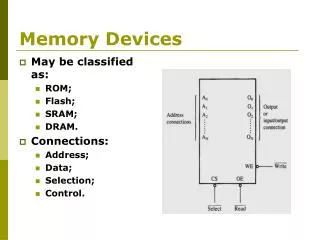
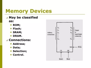
Introduction • Dynamic RAM (DRAM) • Most commonly used type of system memory • Requires refreshing every few milliseconds • Holds data for a very short time • Less expensive than static RAM
Introduction • These are the steps in order to access a cell in DRAM: A row command to latch in Row address A column command to latch in Column address A necessary delay between the two commands as well as a delay after the column command for the I/O circuit to drive valid data.
Introduction • Fast Page Mode (FPM) DRAM • Sending the row address just once for many accesses to memory in locations near each other, improving access time • takes advantage of the fact that when cells within the same row are accessed, the row command doesn’t need to be repeated. • Page mode - operation mode where multiple column commands follow a single row command • Burst mode access - memory is not read one byte at a time (32 or 64 bits at a time), but in several consecutive chunks of memory
FPM/EDO Memory • Read Timing & Memory Access Diagrams
Synchronous DRAM • SDRAM is designed to synchronize itself with the timing of the CPU • take advantage of interleaving and burst mode functions, which make memory retrieval even faster. • SDRAM modules come in several different speeds so as to synchronize to the clock speeds of the systems they'll be used in. • E.g. PC66 SDRAM runs at 66MHz; PC100 SDRAM runs at 100MHz
Burst Mode Feature • Burst Mode • Bursting is a rapid data-transfer technique that automatically generates a block of data (a series of consecutive addresses) every time the processor requests a single address. • The assumption is that the next data-address the processor will request will be sequential to the previous one.
Important Timing Terms • tRP - The time required to switch internal memory banks. (RAS Precharge) • tRCD - The time required between /RAS (Row Address Select) and /CAS (Column Address Select) access. • tAC - The amount of time necessary to "prepare" for the next output in burst mode. • tCAC - The Column Access Time. • tCL - (or CL) CAS Latency. • tCLK - The Length of a Clock Cycle. • RAS - Row Address Strobe or Row Address Select. • CAS - Column Address Strobe or Column Address Select. • Read Cycle Time - The time required to make data ready by the next clock cycle in burst mode. • Note #1: tRAC (Random Access Time) is calculated as tRCD + tCAC = tRACNote #2:RAS and CAS normally appear in technical manuals with an over-line as in RAS or CAS.
SDRAM Read Cycle Clock 1: ACTIVATE the row by turning on /CS and /RAS. (place the proper row address on the address bus – chip will know which row you want to ACTIVATE. Clock 3: READ the column you want from the row you've ACTIVATED by turning on /CAS while placing the column's address on the address bus. Clocks 5-10: The data from the row and column that you gave the chip goes out onto the Data Bus, followed by a BURST of other columns, the order of which depends on which BURST MODE you've set. (More on BURST in a second). tCAC - The Column Access Time tRAC (Random Access Time)
Double Data Rate DRAM • the next generation SDRAM. • DDR reads data on both the rising and falling edges of the clock signal (SDRAM only carries information on the rising edge of a signal) • Data transfer is then twice as fast: i.e. instead of a data rate of 133MHz, DDR memory transfers data at 266MHz. • DDR is not backward compatible with SDRAM-designed motherboards
DDR DRAM • Added circuitry: produces a data output strobe (DQS) • syncs data output to the external clock • allows DDR to transfer the results of a read on both clock edges. • Writes: DQS signal generated by the chipset's memory interface to sync the write data to both edges of the clock
Rambus DRAM • A revolutionary step from SDRAM • Has changes to the bus structure and how signals are carried • Rambus memory sends less information on the data bus (which is 18 bits wide as opposed to the standard 32 or 64 bits) but it sends data more frequently. • It also reads data on both the rising and falling edges of the clock signal, as DDR does. As a result, Rambus memory is able to achieve effective data transfer speeds of 800MHz and higher.
Rambus DRAM • Each RAMBUS chip has only 16 data pins on it, just like an SDRAM chip, which is enough to spit out only two bytes at a time. • How, then, does an RDRAM provide full system bandwidth with only 16 data pins? • Multiplexing is the key to RAMBUS' excellent granularity and low pin count
Multiplexor: sits in between the DRAM core's 16-byte internal data bus and the two, single-byte Data A and Data B buses that make up the two-byte wide RAMBUS data channel. • These muxes take data in 8-byte wide chunks off of the two internal buses and stream them a byte at a time down the 1-byte wide Data A and Data B buses.
RDRAM RDRAM READ: The data from the banks travels over the two, 8-byte core buses, is multiplexed onto the Data A and Data B buses, and then travels out the 16 data pins and onto the 16-bit data bus towards the CPU.