Download
1 / 229
2.29k likes | 2.29k Vues
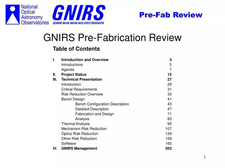
GNIRS Pre-Fabrication Review. Table of Contents I. Introduction and Overview 3 Introductions 5 Agenda 7 II. Project Status 15 III. Technical Presentation 27 Introduction 29 Critical Requirements 31 Risk Reduction Overview 33

E N D
GNIRS Pre-Fabrication Review Table of Contents I. Introduction and Overview 3 Introductions 5 Agenda 7 II. Project Status 15 III. Technical Presentation 27 Introduction 29 Critical Requirements 31 Risk Reduction Overview 33 Bench Design 41 Bench Configuration Description 43 Detailed Description 47 Fabrication and Design 71 Analysis 83 Thermal Analysis 95 Mechanism Risk Reduction 107 Optics Risk Reduction 139 Other Risk Reduction 159 Software 165 IV. GNIRS Management 203 1
Section I Introduction 3
Project Management N. Gaughan, PM D. Eklund, PA M. Bowersock, AA Project Scientist(s) J. Elias, PS D. Joyce, PSS B. Gregory, PSS Electrical –J. Penegor, EE Optical –M. Liang, OE Software –R. Wolff, SM Mechanical G. Muller, Sr. ME E. Hileman, Sr. ME L. Goble, Sr. ME Design Drafting J. Andrew, Sr. TA D. Rosin, DT E. Downey, DT R. Robles, DT Procurement – A. Davis, TA IM – J. Stein,Sr. IM M&P – W. Ditsler, Eng GNIRS Staff 4
Introductions Recognition of Gemini and Visitors Introductions 5
Agenda May 11: Time Subject Presenter 0830 Introduction, opening statements Sidney/Neil Project Status Neil 0930 Technical Presentation: Introduction Jay Critical Requirements Jay Risk Reduction overview Jay 1000 Break 1015 Bench Design - Configuration overview/description Gary - Detailed description Gary - Fabrication and design Gary - Analysis Ed 1200 Lunch 1300 Thermal Analysis Jay 1330 Mechanism risk reduction Jay 1430 Optics Risk Reduction Dick 1500 Other Risk Reduction Jay 1515 Break 1530 Software Richard 1630 End of technical presentations May 12: 0900 GNIRS management Neil/Dan 1100 End/Gemini caucus period 1200 Lunch 6
Agenda • Order of presentations • Breaks • Lunch plans 7
Orientation • The posters on the wall include views of the bench design and prototype hardware. • Also posted is the project plan and WBS. • The materials on the table for your review include the following: • System design notes (SDN’s) • IFU ICD • OIWFS ICD • Motor test report • Prototype lens mount test report • Work scope documents • GNIRS FPRD • Restart Review book • The two workstations have solid models of the bench designs. 8
Orientation • Wall charts • Project plan • WBS • Posters • Materials on the table • Work stations • Demos of solid models of benches and other components • Manned during breaks 9
Overview of the presentation • We will start with the current status of the project including an overview of the project schedule, summaries of the bench design and prototyping efforts, and progress on software. • The risk reduction effort is being conducted to prove the design approaches of our two types of mechanism drives, and camera lens mounting. • Optical bench design will discuss the solid models of the three main components of the bench: Pre-Slit, Post-Slit, and OIWFS. • The structural analysis of these solid models is in process. We will present preliminary results of this analysis. The thermal analysis required to design the bench is complete. • The software section will cover the software plan and software development. • The management section will discuss the project plan/schedule in detail, progress, costs, and procurement. 10
Overview of the Presentation • Current status of the project • Project overview • Risk Reduction effort • Optical bench design and analysis • Software • Management 11
Review Purpose • Assess if optical bench design will meet deflection requirement • Review risk reduction results and assess how these results couple into the actual design • Review scope of software effort and assess if it will meet project requirements • Report on the current status of the project 13
Section II Current Status of the GNIRS Project 15
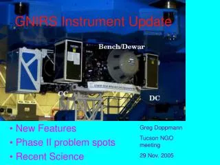
Activities to Pre-Fab Review • Systems engineering - Jay Elias, Dick Joyce • Prototyping; rotary and linear drive, optical mount • Cold motor testing • IFU ICD • Thermal analysis of system • Opto-Mechanical Design - Gary Muller, Ed Hileman, Larry Goble, Designers • Pre-Slit, Post-slit and OIWFS bench solid model design – Larry • Mechanism design and bench design support – Gary • Camera, Filter wheel, Environmental cover, Acquisition mirror, Motor drive • Structural analysis – Larry and Ed • Software Design - Richard Wolff • Software Plan, Component controller • Procurement - Al Davis • Optics/mirrors/filters, Materials 16
Project Status • The project is 21% complete overall. • 90% of the work planned to the Pre-Fab Review has been completed. • We are proceeding in several areas of the project in parallel • We have conducted an intensive effort on bench design and analysis, and proof-of-principal of our mechanism designs and lens mounts. • The planned systems Engineering effort is 70% complete. • We still have work to do to complete the Rotary and Linear prototypes. • The optical bench designs are 100% complete for analysis purposes. • The structural analysis of these benches will be completed shortly after the review. • The software plan is 100% complete, and low-level code development is 40% complete. • Mechanism design is well underway for several mechanisms • Procurement of optics, mirrors, filters, gratings, materials, etc., is as per plan. 19
Project cost performance • Budgeted labor dollars - August ’99 to the PFR is 60% spent • Hours budgeted = 21,678 hrs; hours expended = 14,871 hrs • Rate charged = $33.10/hr; planned at $38/hr • Budgeted capital dollars is 75% spent • Performance Aug ’99 through April ’00 (based on MS Project % complete data) • BCWS = $383,515 (budgeted cost of work scheduled) • BCWP = $617,998 (budgeted cost of work performed) • ACWP = $492,192 (actual cost of work performed) (cas) • CPI (BCWP/ACWP) =1.26 Cumulative CPI =1.12 • SPI (BCWP/BCWS) =1.61 • A project forecast-to-completion was done in April • The projected delivery date has not changed - still July-Aug 2002 • The total projected project cost is nearly the same • Remaining cost to go is about $3.1M (labor and capital) • Baseline estimate was ~$4.25M from Jan’99 to completion • Current forecast cost estimate is ~$4.12M 21
Project Plan Components • Systems Engineering effort • Prototyping • Structural and thermal analysis • Bench Design design and fabrication • Mechanism design, fabrication and test • Fixed Assemblies design and fabrication • Electronics design, fabrication and test • Software design, code and test/debug • Integration and test • The summary plan is a roll-up of the detailed plan. 22
Summary plan 23
Conclusions • Project plan and schedule show that we are on track to deliver on schedule in summer 2002. • Project cost tracking show that the project is under-spending. • We have adequate staff to do the job. • The estimated cost of the project has not significantly changed from the baseline established in August ’99. We will spend on the order of $4.1M from January ’99 until the time we complete the instrument. • Details and expansion of project management items will be provided tomorrow morning. 24
Technical Presentation • The design of the instrument is conservative, and there are no known technological showstoppers. The effort centers around the execution of design, fabrication, and test per the plan. • The purpose of the presentation is to demonstrate that bench design and supporting analysis are sound and that we have conducted sufficient prototype investigations to proceed. 25
Section III Technical Presentation 27
Technical Presentation Critical Requirements Risk Reduction Overview Bench Design and Analysis Thermal Analysis Prototyping Other risk reduction Software 29
Critical Requirements Identified Gravity deflection - 3 requirements (from RR review and before) list - 2 affect bench OIWFS maintains object on slit (12 microns (0.02 arcsec) motion in 1 hour) Spectrum (slit image) doesn’t move on detector (0.1 pixel=2.7 microns in hour) Secondary image motion at cold stop +/-1% overall (less stringent but involves interface to warm structure and to ISS) Thermal performance Cool-down time (Maximum 4 days) Temperature gradients (preservation on alignment, several degrees OK) Temperature variations (limit flexure, defocus - need <1 K) Mechanism performance Repeatability (10 pixels for reconfigurations, 0.1 pixels for acquisition) Flexure (0.1 pixel pixel, includes mechanism “play”) Thermal (cooling time constant, heating from motor/drive) Opto-mechanical performance Lens cooling Lens positioning (stability under thermal cycling within tolerances) Lens stresses (500 psi or less) 30
Critical Requirements Identified Gravity Deflection Thermal Performance Mechanism Performance Opto-mechanical performance 31
Risk Reduction - Overview What are the risks? How did we address them? 33
Risk Reduction Plan Systems Engineering: Systems approach used to identify areas of risk (some help from review committees!) and isolate specific issues. Prototypes vs. analysis: Identify those issues where analysis provides good answers as opposed to those where prototyping is better. Example: use FEA for rigid structures (bench), but need prototypes to model situations where contact properties dominate effects (turrets). Test Plans and Procedures: Prototype work designed to answer specific questions, need focussed test plan to ensure that questions are thoroughly investigated, avoid wasted effort. Results Applied to Design: Experience with prototypes may show that a design works “as is”. May also suggest design improvements, but these are implemented only if the design would not meet requirements otherwise or redesign leads to faster schedule or lower cost. Prototype does not need rework to meet requirements if design change to meet requirements involves minimal risk. 36
Risk Reduction Plan Systems Engineering Prototypes vs. Analysis Test Plan and Procedures Results Applied to Design 37
Risk Reduction Plan 5 Areas Involved Flexure Analysis Thermal Analysis Mechanical Prototypes Systems Approach to Design Early Procurement 39
Optical Bench Design Agenda •Design Overview •Pre-Slit Bench Assembly •Post-Slit Bench Assembly •OIWFS Bench Assembly •Fabrication Issues Example of systems approach to design 41
Bench Configuration Overview Bench structure comprises Pre-slit bench (pick-off mirror to and including slit/IFU) Post-slit bench (from slit to detector) OIWFS bench (field lens to OIWFS detector) Mechanisms/optical assemblies Offner relay (includes pick-off mirror) Filter wheels Slit/IFU slide and Decker assembly Collimator Acquisition mirror Prism turret Grating turret Camera turret Long camera external fold mirrors Detector mount/focus stage 42
Configuration Overview Red ray: Spectrograph Blue ray: On-Instrument Wave Front Sensor 43
Configuration Overview Red ray: Spectrograph Blue ray: On-Instrument Wave Front Sensor 45
Exploded view of bench structure • All bench structure machined from single billet. • Bench structure designed for ease of fabrication. • Machining techniques considered during design process. • Pocket depth to tool diameter ratios, radiused pockets, etc • Stiffness obtained when components are fastened together. 46
Bench Design Drivers • •Stiffness • Minimize deflections • •Weight • Goal: Minimize weight of cold bench for minimal cool-down cycle • Weight budget • •Envelope • Fit within Gemini instrument envelope • •Mechanism access • Modular mechanisms for ease of installation/removal • Mechanisms accessible without disassembly of bench • •Motor access • Cold strapping, wiring • External to light tight bench • •Fabrication • Use proven technologies, minimize risk, optimize schedule • Minimize bolted joints • Optimal thermal conductivity, control tolerances, homogeneous structure 49