Download
1 / 14
140 likes | 235 Vues
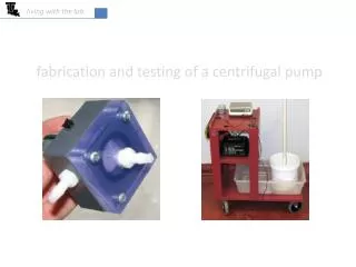
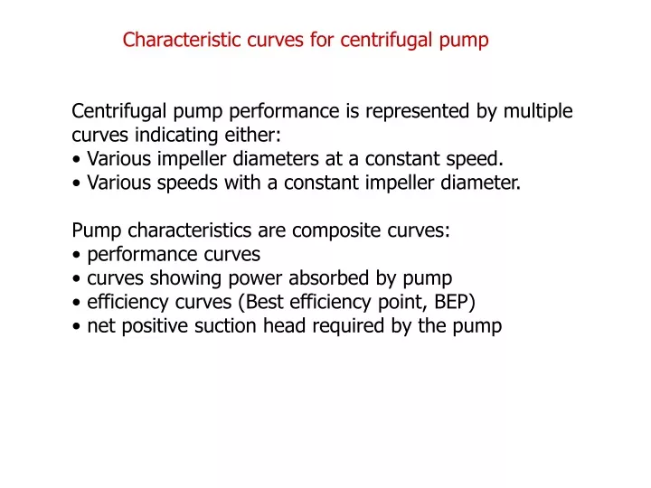
Characteristic curves for centrifugal pump. Centrifugal pump performance is represented by multiple curves indicating either: • Various impeller diameters at a constant speed. • Various speeds with a constant impeller diameter. Pump characteristics are composite curves: • performance curves

E N D
Characteristic curves for centrifugal pump Centrifugal pump performance is represented by multiple curves indicating either: • Various impeller diameters at a constant speed. • Various speeds with a constant impeller diameter. Pump characteristics are composite curves: • performance curves • curves showing power absorbed by pump • efficiency curves (Best efficiency point, BEP) • net positive suction head required by the pump
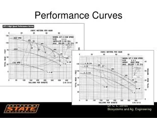
1. Maximum recommended head. 2. Minimum recommended head. 3. Minimum recommended flow. 4. Maximum recommended flow.
"BEP" - Best Efficiency Point is not only the operating point of highest efficiency but also the point where velocity and therefore pressure is equal around the impeller and volute. As the operating point moves away from the Best Efficiency Point, the velocity changes, which changes the pressure acting on one side of the impeller. This uneven pressure on the impeller results in excess load, and reduces the service life. Outside the operating range cavitation can be created. The actual system curve may cross the pump curve inside the recommended operating range.
System curve or system characteristics Head – flowrate function In general the pump has to supply enough energy to: • lift water through a certain height – the static heightHs • overcome losses dependent on the discharge, Q. Thus the system head is: Typically, losses (whether frictional or due to pipe fittings) are proportional to Q2, so that the system characteristic is often quadratic:
Duty Point The pump operates at a duty point(oroperatingpoint) where the head supplied by the pump precisely matches the head requirements of the system at the same discharge; i.e. wherethe pump and systemH-Q characteristics intersect. The pump can not develop pressure unless the system creates backpressure (ie: static, and /or friction loss).
Example A water pump was tested at a rotation rate of 1500 rpm. The following data was obtained. (Qis quantity of flow, His head of water, h is efficiency). It is proposed to used this pump to draw water from an open sump to an elevation 5.5 m above. The delivery pipe is 20.0 m long and 100 mm diameter, and has a friction factor of 0.02. If operating at 1500 rpm, find: (a) the discharge that the pump can provide; (b) the pump efficiency at this discharge; (c) the input power required.
Affinity laws Relationships for the estimation of changes in pump performance as a result of a change in one of the basic pump parameters, e.g. shaft speed and impeller diameter.
Affinity laws Law 1. With impeller diameter (D) held constant: Law 1a. Flow is proportional to shaft speed: Law 1b. Pressure or Head is proportional to the square of shaft speed: Law 1c. Power is proportional to the cube of shaft speed:
Affinity laws Law 2. With shaft speed (N) held constant: Law 2a. Flow is proportional to the impeller diameter : Law 2b. Pressure or Head is proportional to the square of the impeller diameter : Law 2c. Power is proportional to the cube of the impeller diameter :
Pumps in parallel Same head: H Add the discharges: Q1 + Q2 Advantages of pumps in parallel are: • high capacity: permits a large total discharge; • flexibility: pumps can be brought in and out of service if the required discharge varies • redundancy: pumping can continue if one is not operating due to failure or planned maintenance.
Pumps in series Same discharge: Q Add the heads: H1 + H2 Pumps in series may be necessary togenerate high heads, or provide regular „boosts” along long pipelineswithout large pressures at any particular point.