Download
1 / 18
190 likes | 199 Vues
Materials Testing With a High-Q RF Cavity. Sami Tantawi, Christopher Nantista, Valery Dolgashev, Gordon Bowden, Ricky Campisi, T. Tajima, and P. Kneisel. Work supported by the U.S. Department of Energy under contract DE-AC02-76SF00515. Abstract.

E N D
Materials Testing With a High-Q RF Cavity Sami Tantawi, Christopher Nantista, Valery Dolgashev, Gordon Bowden, Ricky Campisi, T. Tajima, and P. Kneisel Work supported by the U.S. Department of Energy under contract DE-AC02-76SF00515.
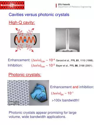
Abstract Superconducting rf is of increasing importance in particle accelerators. We have developed a resonant cavity with high quality factor and an interchangeable wall for testing of superconducting materials. A compact TE01 mode launcher attached to the coupling iris selectively excites the azimuthally symmetric cavity mode, which allows a gap at the detachable wall and is free of surface electric fields that could cause field emission, multipactor, and rf breakdown. The shape of the cavity is tailored to focus magnetic field on the test sample. We describe cryogenic experiments conducted with this cavity. An initial experiment with copper benchmarked our apparatus. This was followed by tests with Nb and MgB2. In addition to characterizing the onset of superconductivity with temperature, our cavity can be resonated with a high power klystron to determine the surface magnetic field level sustainable by the material in the superconducting state. A feedback code is used to make the low level RF drive track the resonant frequency. We will also use our resonant cavity design to study the effects of high power pulsed heating on normal conducting surfaces.
Finding the Right Cavity Shape TE01n pillbox (field same on top and bottom)
The Mushroom Cavity TE013-like mode peak |E| |H| 57.1% peak 54.5% peak |Hs| axis Q0 = ~44,000 (Cu, room temp.) contour (inches) bottom plate material sample r = 0.98” • Features: • No surface electric fields (no multipactor) • Magnetic field concentrated on bottom (sample) face (75% higher than anywhere else) • Purely azimuthal currents allow demountable bottom face (gap). • Why X-band (~11.424 GHz)?: • high power & rf components available • fits in cryogenic dewar • small (3”) samples required
Other Nearby Resonance Modes: 6.8% mode separation for axisymm. TE modes. 4.0% mode separation from axisymm. TM mode. 1.4% mode separation from non-axisymm. mode. TE131 TM32? WC150 (3.81 cm diam.) Couple on axis with pure axisymmetric tranverse electric mode TE01 in circular waveguide.
Mechanical Design WC150 ss Conflat flanges Cu Sample Dimensions copper plug temperature sensor G. Bowden
WR90-WC150 Compact High-Purity TE01 Mode Launcher TE10 TE01 rect.-to-circ. TE20TE01 mode converter WR90 height taper (.400”.800”) planar TE10TE20 converter WC150 V. Dolgashev
Assembly Cryogenic Dewar WR90 waveguide inner diameter ~1 ft. mode converter vacuum can removed (cavity immersed in liquid He) cavity different cavity
“Cold” Tests (Room Temperature) room temp. measurements HP 8510C Network Analyzer Nb sample mounted in bottom flange
Processing Cold Test Data Complex S11 is measured with 1601 points in 1 megaherz around resonance. Phase slew due to input waveguide, determined from a 50 MHz measurement is subtracted from 1 MHz data. A “Q circle” is fit to the corrected S11 data in the complex plane to determine fr, b, and QL are determined. From these Q0 and Qe are derived. Temperature measured with a carbon-glass resistor (low end) inserted into a hole in bottom of cavity and from frequency shift (higher temperatures).
Copper Sample Q0: 44,000 190,300 Niobium Sample Q0: 25,600 330,700
Transition of Cavity Q During Warmup from Liquid He Temperature 9.3 K
Needed Power 56.76% H field along radius of bottom face • If |Bc|=180 mT, then |Hc|=143.25 kA/m, • Uc 0.43607J = 8.754×10⁻⁷s Pc for a 1.5 ms flat input pulse. • Pc498 kW U=8.72265×10⁻¹⁷ J |Hmax|2 = 4.1048×10⁻⁶ A2/m2 |Hmax|2 = AU A = 4.7059×10¹⁰ A2/m2/J
High Power Test of Niobium at 4.2K New test setup for inexpensive accurate characterization of high-field RF properties of materials and processing techniques
High Power Testing An initial high power experiment was performed, but data has not yet been fully analyzed. A feedback code is used to make the low level RF drive track the resonant frequency by flattening the phase during cavity discharge. Quenching of Nb sample seen as a roll off of Q as power was raised. Our experimental setup is still maturing. We will add a high-power circulator to isolate the klystron from the cavity reflection. We will also add a silicon diode and a Cernox temperature sensor. We will soon test a sample of MgB2 provided by T. Tajima et al. of Los Alamos. This material is supposed to have an order of magnitude lower surface resistance than niobium at 4K and a critical temperature of ~40K, compared to 9.2K for niobium.
Pulsed Heating Our cavity design also recommends itself to pulsed heating experiments (á la Pritzkau and Siemann). We will conduct a set of such experiments, using a second cavity designed to be nearly critically coupled at room temperature. These will be done in collaboration with W. Wuench, et al. of CERN, who will provide samples of copper, copper zirconium, etc. Stored Energy / Input Power (J/W) Room Temperature Design 5.175×10⁻⁷ • a=1.032, • Tc=0.5915ms
(Pritz. (3.34)) 11.92 MW 100°C Cu parameters held constant in this calculation. We have plenty of power to create pulsed heating temperature rises on the order of 100 °C.
Conclusions • We have designed and fabricated a compact, high-Q rf cavity optimized for economically testing the rf properties of material samples and their dependence on temperature and field by means of frequency and Q monitoring. • We’ve performed low power cryogenic tests with copper and niobium samples. • High power tests are under way. • A similar cavity will be used for pulsed heating material testing.