Download
1 / 11
110 likes | 114 Vues
This article discusses optical diagnostics in tight and high radiation environments, where only passive optical components are used. The transmission of images through a flexible fiber bundle is also explored. The use of imaging fibers from Fujikura and Sumitomo, as well as the Hawkeye flexible borescope, are mentioned. The article also covers the use of SMD cameras and the comparison of image quality. Furthermore, the article discusses studies on the irradiation of optical components and the use of an optical chopper in motion.

E N D
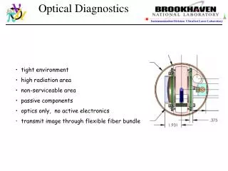
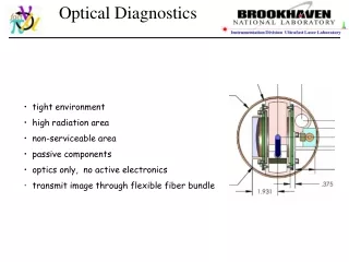
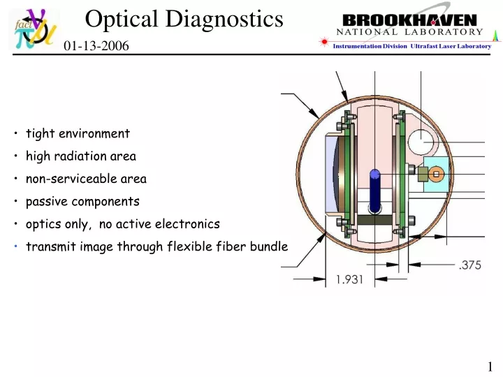
Optical Diagnostics 01-13-2006 • tight environment • high radiation area • non-serviceable area • passive components • optics only, no active electronics • transmit image through flexible fiber bundle 1
Optical Diagnostics optical design in secondary containment e-Drawing - Van Graves, ORNL One set of optics per viewport Conceptual design completed • issues on the imaging fiber bundle 2
Sumitomo imaging fibers IGN-08/20 - sample All have small imaging area <2 mm diameter 4
More imaging fibers (glass) Hawkeye flexible borescope 18,000 glass fibers fiber diameter 6 μm bundle diameter ~ 1-mm 8-mm outer diameter FOV 40 deg DOF 15-mm to infinity Length: 1-meter SMD camera CCD size: 13.4 x 13.4 mm Pixels: 960x960 Single frame: 240x240 pixels 57,600 picture elements Reduced pixel size: 56 x 56 um total fiber counts ~18,000 in 1 mm diameter Imaging ~150 x 150 fibers on 240 x 240 CCD array ~1 imaging fiber on ~1.6 pixel on a single frame 5
borescope retroreflected illumination cm scale 6
laser borescope retroreflected illumination SMD-64KIM camera 16 frames, at 10 µs/frame, exposure time 0.15 μs total fiber counts ~18,000 in 1 mm diameter Imaging φ=150 fibers on 240 x 240 CCD array ~1 imaging fiber on ~1.6 pixel on a single frame 7
image quality comparison Sumitomo 30,000 fibers image ?? SMD-64KIM camera 16 frames, at 10 µs/frame, exposure time 0.15 μs 18,000 glass fibers, flexible 50,000 glass fibers, image conduit 8
Optical Diagnostics An optical chopper in motion @ 4 kHz Stationary image 100 µs/frame Velocity @ ~40 m/s 10 µs/frame 1 µs/frame 100 µs/frame with reflective mask 9
Irradiation Studies of Optical Components - II CERN, week of Oct. 24, 2005 1.4 GeV proton beam 4 x 10 15 proton Irradiation dose: equivalent to 40 pulses of 24 GeV proton beam 28 TP/pulse total of 1.2 x 10 15 proton after before Sumitomo imaging fiber 30,000 pixel is rad-hard to 1Mrad 10 total fiber counts ~30,000 in 0.72 mm diameter imaging φ=195 fibers on 240 x 240 CCD array ~1 imaging fiber on ~1.2 pixel on a single frame
One set of optics per viewport • tight environment • high radiation area • non-serviceable area • passive components • optics only, no active electronics • transmit image through flexible fiber bundle 11