Download
1 / 36
370 likes | 900 Vues
Tankless Rack System By Rinnai. Ojective of Rack System. Rinnai’s objective:

E N D
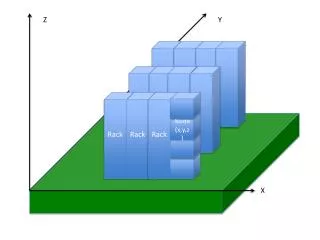
Ojective of Rack System Rinnai’s objective: To supply a packaged water heater solution as fully assembled systems. The system/kit would include all water/gas connections and manifolds under the units. Installer mounts rack system with any necessary venting and connects his utilities at which time the system is ready for operation • Offerings to include; • In-Line or Wall Mount – 2 & 3 unit rack • Back to Back Mount; 2 – 4 or 3 - 6 unit rack • Rack systems can be combined in combinations up to 25 water heaters.
Features & Benefits • Features and Benefits: • Pre-assembled rack with water heaters installed • Racks can be used with RU98 indoor/outdoor water heaters ONLY • In-Line or Back to Back free standing options • Gas and water manifolds properly sized for each rack system • Rinnai MSB electronic control system available for linking up to 25 units • MCC-91-2 commercial controller available for temperatures between 140˚F and 185˚F
Features & Benefits • Features and Benefits continue: • Flexible gas/water lines • Drain tees for gas sediment traps • Reinforced eyelets on back to back racks for lifting purposes • Marine grade powered coated aluminum racks • Fully assembled TRS (with water heaters) is designed to fit through a standard 32 inch door
Back to Back Assembly Actual 4 Unit Back to Back Rack Assembly
Integrated Manifold Integrated Manifolds for both In-line and Back to Back Rack Systems
In-Line Frame Design Top Frame Center Frame • Uni-Strut Vertical legs /Sheet Metal bracing. • Uni-Strut – Galvanized Steel • Sheet Metal is 0.090” Aluminum w/powder coat • Frame uses (12) 5/16” threaded bolts to secure the top and center bracing. • Use up to #10 screws to mount to wall studs, 0.219” holes are 2” apart for ease of installation
Manifold Data • Manifold Kits • Hot & Cold Water – Type “L” Copper • Manifolds properly sized to handle maximum flow of system • Universal manifold for hot /cold water lines • Gas – Black Iron w/powder coat • Branch Lines • CSST ¾” from water heaters to manifolds - all connections • RIK kits include for hot/cold water feeds to manifold. • ¾” manual shut off or service valve provided for each water heater • ¾” CSST gas branch lines with yellow epoxy coating
Lifting Points Proper lifting points for Rack Systems Back to Back lifting requirements In-Line lifting requirements - place straps here
MSB System • REU-MSB Control System: • The MSB-M main board is supplied with (2) MSB-C1 cables, (one short & one long) to connect the first two units up to the main MSB-M board. • Additional MSB-C1 cables will be needed to connect a third, forth or fifth unit to a MSB board. If installing more than five units the combination of MSB-M boards plus C1 and C2 cables will be determined on site based on the water heater configuration you choose. • Up to 5 MSB-M boards can be linked together with communication cables (MSB-C2’s) allowing up to 25 water heaters to operate as a single system. • An MSB system could have an operating range from 10,000 BTU to as great as 5 million BTU’s in terms of flow rate, from 0.4 gpm to 245 gpm. • When multiple water heaters are linked together with MSB controls, they will attempt to supply equal amounts of hot water. They will also rotated occasionally to ensure equal usage among the entire system. • On initial water flow 1 to 3 units will fire up based on the dip switch configuration of the Main MSB board. Once the flow rate is determined, the MSB board will cycle additional units on or off as needed. Water heaters not firing will close their servo valves.
MSB System • MSB Control System continue • The temperature setting for all water heaters in a manifold system are controlled by the primary unit connected to the Main MSB board. The temperature controllers connected to other units will display the set temperature selected on the primary unit and cannot be adjusted individually. Additionally they will display error codes and can be used for diagnostics for that particular unit. • If a water temperature over 140 ˚F is desired, the MCC-91-2 controller must be installed on the water heater with the Main MSB board. • Dip switches on the MSB-2M board determine the number of units in standby. It is recommended • that the Main MSB-M board dip switches are set for three units to be in the standby mode. All other • MSB-M boards should be set to one unit in standby. Place dip switch #1 and #2 on the Main MSB-M • board to the “OFF” position, this will place three units in the standby mode. Place dip switch #1 & #2 • to the other MSB-M boards to the “ON” position. That will place one unit in those banks in the • standby mode. The system will always allow three units to be in standby, as long as the Main MSB-M • board is set to three units as explained above.
MSB System • MSB Control System (continued) • All MSB boards must be set up to communicate with the other boards. This is achieved by setting the dip switches on the MSB boards to the proper positions, follow steps a – e below: • Set dip switch #3 on the Main MSB board to the “ON” position. • Set dip switch #4 on the second MSB board to the “ON” position. • Set dip switch #3 & #4 on the third MSB board to the “ON” position. • Set dip switch #5 on the fourth MSB board to the “ON” position. • Set dip switch #3 & #5 on the fifth MSB board to the “ON” position LED #6 Dip switches In all steps, LED #6 will light to confirm connection.
In-Line TRW02 Specifications TRW02 Specifications In-Line TRW02 Water and gas flex lines are included on all rack systems.
In-Line TRW02 Dimensions TRW02 Dimensions
In-Line TRW03 Specifications TRW03 Specifications In-Line TRW03 Water and gas flex lines are included on all rack systems.
In-Line TRW03 Dimensions TRW03 Dimensions
TRR04 Specifications Back to Back TRS04 Specification Back to Back TRS04 Water and gas flex lines are included on all rack systems.
TRS04 Dimensions Back to Back TRS04 Dimensions
TRS06 Specifications Back to Back TRS06 Specification Back to Back TRS06 Water and gas flex lines are included on all rack systems.
TRS06 Dimensions Back to Back TRS06 Dimensions
Rack System Examples Back to Back Application In-Line Application
Rack System Examples Back to Back Application
Rack System Examples Back to Back Application
Clearances for Water Heaters Install the rack system per clearances shown below for the RU98i and RU98e water heaters Indoor models: RU98i Outdoor models: RU98e
Piping Layout - 24 Units Manifold Design for 24 W/H’s 2 ½”, 4” and 6” Water Manifolds/Connections Multiple rack systems MUST pipe in parallel as shown below. Piping systems in series will result in undersized water/gas lines.
Rack System Kit Components Tankless Rack System Kit Components
Rack System Kit Components Tankless Rack System Kit Components
Rack System Kit Components Tankless Rack System Kit Components
Material Details Material Detail List
Material Details Material Detail List
Material Details Material Detail List
Materials Details Material Detail List
Material Details Material Detail List continue from previous slide
Electrical/Flow Ratings Electrical /BTU Input Ratings
The End Rinnai Rack System Training Version 02282014GW