Download
1 / 28
300 likes | 702 Vues
Case-New Holland. Steer-by-Wire Detailed Design. Today’s Agenda. Who is CNH? Background Project Goal System Level Concept Design Components Detailed Concept Validation of Concept Superiority Resources and Cost Summary of Results What’s Next?. Who is CNH?.

E N D
Case-New Holland Steer-by-Wire Detailed Design
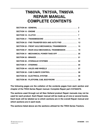
Today’s Agenda • Who is CNH? • Background • Project Goal • System Level Concept • Design Components • Detailed Concept • Validation of Concept Superiority • Resources and Cost • Summary of Results • What’s Next?
Who is CNH? • One of the world leaders in Agricultural Equipment. • Various locations world wide. • The Technical Center is located in New Holland, PA.
Background Current Steering System The system is currently a purely mechanical linkage from operators hand to hydrostatic pumps.
Project Goal Goal is to remove mechanical linkage and replace with a lower cost, expandable, steer-by-wire system
Can customize software to specific needs Future possibility of GPS navigational driving Removal of expensive mechanical linkage Less component wear and tear Lowers manufacturing cost Why Steer By Wire?
System Level Concept and Project Scope Steering Column Wheels Pumps Project Scope 2 Independent Output Channels Sensor: Reads Angular Displacement ECU Power Source
Key Metrics 1.) Production Price: < $90.00 2.) Accuracy: ± 1° 3.) Resolution: ± 0.5° 4.) Temperature Range: -40° - 180° F
Concept Components • Mounting Location • Sensor Selection • Shaft Extension Design • To hold sensor and viscous damper • Mounting Bracket Design • To incorporate a “real-feel” and prevent CNH from having to heavily modify our design at a later time, we will integrate a viscous damper into our design.
Mounting Location Top Knuckle • Maximum depopulation • Completely encased in the steering column • Will require significant structural alterations • Limited room for mounting Below Cab • Least structural alterations to steering column structure • Most serviceable • Exposed to elements • Limited depopulation Boot • Minimal structural alterations to steering column structure • Least space restrictions • May be prone to vibration
Mounting Location Boot • Minimal structural alterations to steering column structure • Least space restrictions
Sensor Selection • Proximity: • Possibility of machining a cam or screw onto shaft and measuring distance to decipher turning degrees • Magnetic Hall Effect • End Mount • BEI Duncan Electronics’ 9900 Series Dual Output Hall Effect Sensor • Feed-Through Mount • Delphi’s Non-Contact Multi Turn Rotary Position Sensor • BEI Duncan Electronics’ Non-Contacting Angular Position Sensor (NCAPS).
Sensor Selection BEI Duncan NCAPS • Due to time and cost issues, the Non-Contacting Angular Position Sensor (NCAPS) currently in production will be used for the prototype. • Current NCAPS does not meet redundancy requirement, however, for production a custom made sensor that meets all requirements will be used. • BEI Duncan design engineers are currently working on the design of this custom sensor
Shaft Extension Detailed Design of Shaft • Material: Aluminum • 3/8” diameter with ¼” flats. • End will be machined down to 5/16” and force fit into the splined end of the current shaft with a roll pin that will ensure rotational unison. • Sensor will have a Collar that will adapt to the 3/8” shaft.
Shaft Extension Justification • Performed a Finite Element Analysis (FEA) on the shaft using SolidWorks • Determined that the shaft will have a static displacement of 7x10⁻⁵ inches and an angular displacement of 9.408x10⁻⁵ degrees in maximum torsion at the end of the shaft.
Mounting Bracket Detailed Design of Mounting Bracket • Material: Alloyed Steel • Purpose of Bracket is to secure sensor and damper to steering column • 2 piece Mounting Bracket • First Holds the Damper in place • Second Holds the Sensor in place • Secured with four bolts to steering column framework
Viscous Damper • The damper will add the “real-feel” desired for the steering system. • Safely and quietly controls rotary motion • (0.4 – 4.5 Nm.) of Torque per unit is available • Maximum Torque experienced will be approximately 2 Nm
Validating the Concept • A prototype was built using components designed by the Senior Design team and supplied by CNH • Tested with Labview software • Output signal from sensor compared with the output of a “Truthing Sensor” • Optical Encoder was used as the “Truthing Sensor” • The Prototype will eventually be installed into CNH Windrower for on track test!!!
Test Data First graph shows the output of the sensor and encoder vs. time. Second graph shows the difference between the two outputs Third graph shows the derivative of the BEI sensor output.
Test Data Analysis • From the data we determined that there is a difference of approximately ±5° between the two sensors when there is rotation. • There is a consistent error in the same portion of each revolution which leads us to believe that there are imperfections in the shaft alignment. • Testing of run out with a dial indicator located where the sensor is positioned on the shaft showed 0.02” TIR. • Testing of run out with a dial indicator located directly after the last bearing showed .001” TIR. • Through testing of relative angle change resulting from linear displacement of the Rotor we found that there is an error of 1°.
CNH BEI Sensor for prototyping Fabricated bracket for mounting of sensor Testing of prototype for temperature requirements, reliability, drift, and EMC Senior Design Team Building of Prototype Steering Column Testing of resolution, repeatability, and accuracy were done using UofD PC running Lab View Resources
Prototyping Cost • Sensor for Prototyping: $300.00 • Sensor for CNH Preliminary testing: $300.00 • Mounting Stand: $45.00 • Shaft Extension: Freebee • Bracket for mounting Sensor: $10.00 • Truth Sensor: Freebee • CNH Testing: $17,500.00 est. • Miscellaneous Hardware: $10.00 Total Estimated Cost $19,000.00
Sensor: $70.00 est. Shaft Change: $5.00 est. Brackets for mounting Sensor: $5.00 est. Miscellaneous Hardware: $5.00 est. Steering Column Depopulation: ≈-$10.00 est Total Estimated Unit Cost $75.00 CNH Target Unit Cost $90.00 Estimated Unit Production Cost
Path Forward • Turnover of prototype and project to CNH • Design interfaced with servo motor to pump project • Safety and track testing • Ongoing conversation with BEI for custom sensor delivery