Download
1 / 71
710 likes | 859 Vues
Routing in layer-two networks IP addressing Routing algorithms Intra-domain and inter-domain routing Unicast and multicast routing. Lecture03: Network layer and Routing. Routing in layer-two networks IP addressing Routing algorithms Intra-domain and inter-domain routing

E N D
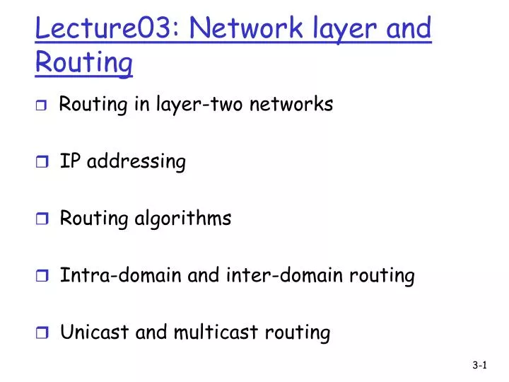
Routing in layer-two networks IP addressing Routing algorithms Intra-domain and inter-domain routing Unicast and multicast routing Lecture03: Network layer and Routing
Routing in layer-two networks IP addressing Routing algorithms Intra-domain and inter-domain routing Unicast and multicast routing Lecture03: Network layer and Routing
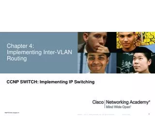
Routing vs. Forwarding • Routing: control plane • Computing paths the packets will follow • Routers talking amongst themselves • Creating the forwarding tables • Forwarding: data plane • Directing a data packet to an outgoing link • Using the forwarding tables
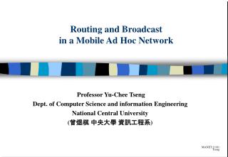
Link layer routing: Spanning Tree • One tree that reaches every node • Single path between each pair of nodes • No loops, so can support broadcast easily • But, paths are long, and some links not used
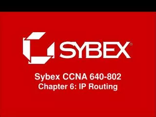
Link layer host discovery: learn and flood • When a frame arrives • Associate address with the incoming interface • When the frame has an unfamiliar destination • Forward out all interfaces B B C A A C Switch learns how to reach A. When in doubt, shout! D D Used in Ethernet LANs
delivers segments from sending to receiving host network layer protocols in every host, every router network data link physical network data link physical network data link physical network data link physical network data link physical network data link physical network data link physical network data link physical network data link physical network data link physical network data link physical application transport network data link physical application transport network data link physical Network layer routing
routers: no state about end-to-end connections packets forwarded using destination host address application transport network data link physical application transport network data link physical Datagram networks 1. Send data 2. Receive data
Routing in layer-two networks IP addressing Routing algorithms Intra-domain and inter-domain routing Unicast and multicast routing Lecture03: Network layer and Routing
Forwarding table 4 billion possible entries Destination Address RangeLink Interface 11001000 00010111 00010000 00000000 through 0 11001000 00010111 00010111 11111111 11001000 00010111 00011000 00000000 through 1 11001000 00010111 00011000 11111111 11001000 00010111 00011000 00000000 through 2 11001000 00010111 00011111 11111111 otherwise 3
IP address: 32-bit identifier for host, router interface interface: connection between host/router and physical link router’s typically have multiple interfaces host typically has one interface IP addresses associated with each interface 223.1.1.2 223.1.2.1 223.1.3.27 223.1.3.1 223.1.3.2 223.1.2.2 IP Addressing: introduction 223.1.1.1 223.1.2.9 223.1.1.4 223.1.1.3 223.1.1.1 = 11011111 00000001 00000001 00000001 223 1 1 1
IP address: subnet part (high order bits) host part (low order bits) What’s a subnet ? device interfaces with same subnet part of IP address can physically reach each other without intervening router Subnets 223.1.1.1 223.1.2.1 223.1.1.2 223.1.2.9 223.1.1.4 223.1.2.2 223.1.1.3 223.1.3.27 subnet 223.1.3.2 223.1.3.1 network consisting of 3 subnets
Recipe To determine the subnets, detach each interface from its host or router, creating islands of isolated networks. Each isolated network is called a subnet. 223.1.1.0/24 223.1.2.0/24 223.1.3.0/24 Subnets Subnet mask: /24
host part subnet part 11001000 0001011100010000 00000000 200.23.16.0/23 IP addressing: CIDR CIDR:Classless InterDomain Routing • subnet portion of address of arbitrary length • address format: a.b.c.d/x, where x is # bits in subnet portion of address Network Layer SSL (8/09)
IP addresses: how to get one? Q: How does network get subnet part of IP addr? A: gets allocated portion of its provider ISP’s address space ISP's block 11001000 00010111 00010000 00000000 200.23.16.0/20 Organization 0 11001000 00010111 00010000 00000000 200.23.16.0/23 Organization 1 11001000 00010111 00010010 00000000 200.23.18.0/23 Organization 2 11001000 00010111 00010100 00000000 200.23.20.0/23 ... ….. …. …. Organization 7 11001000 00010111 00011110 00000000 200.23.30.0/23 Network Layer SSL (8/09)
IP addresses: how to get one? Q: How does host get IP address? • hard-coded by system admin in a file • Wintel: control-panel->network->configuration ->tcp/ip->properties • UNIX: /etc/rc.config • DHCP:Dynamic Host Configuration Protocol: dynamically get address from a server • “plug-and-play” Network Layer SSL (8/09)
IP addressing: how to get one? (cont.) • ICANN (Internet Corporation for Assigned Names and Numbers)/IANA (Internet Assigned Numbers Authority) • allocates addresses • manages DNS • assigns domain names, resolves disputes • Regional, national, and local Internet registries, and ISPs • End-user organization can be assigned IP address space from one of the above Network Layer SSL (8/09)
200.23.16.0/23 200.23.18.0/23 200.23.30.0/23 200.23.20.0/23 . . . . . . Hierarchical addressing: route aggregation Hierarchical addressing allows efficient advertisement of routing information: Organization 0 Organization 1 “Send me anything with addresses beginning 200.23.16.0/20” Organization 2 Fly-By-Night-ISP Internet Organization 7 “Send me anything with addresses beginning 199.31.0.0/16” ISPs-R-Us
200.23.16.0/23 200.23.18.0/23 200.23.30.0/23 200.23.20.0/23 . . . . . . Hierarchical addressing: more specific routes ISPs-R-Us has a more specific route to Organization 1 - this is the reason for longest prefix match. Organization 0 “Send me anything with addresses beginning 200.23.16.0/20” Organization 2 Fly-By-Night-ISP Internet Organization 7 “Send me anything with addresses beginning 199.31.0.0/16 or 200.23.18.0/23” ISPs-R-Us Organization 1
Rapid growth of forwarding table size due to address fragmentation from • Multi-homing • reliability • load balancing
NAT: Network Address Translation rest of Internet local network (e.g., home network) 10.0.0/24 10.0.0.1 10.0.0.4 10.0.0.2 138.76.29.7 10.0.0.3 Datagrams with source or destination in this network have 10.0.0/24 address for source, destination (as usual) All datagrams leaving local network have same single source NAT IP address: 138.76.29.7, different source port numbers Network Layer SSL (8/09)
NAT: Network Address Translation • Motivation: local network uses just one IP address as far as outside world is concerned: • just one IP address needed for all devices • can change addresses of devices in local network without notifying outside world • can change ISP without changing addresses of devices in local network • devices inside local net not explicitly addressable, visible by outside world (a security plus). Network Layer SSL (8/09)
2 4 1 3 S: 138.76.29.7, 5001 D: 128.119.40.186, 80 S: 10.0.0.1, 3345 D: 128.119.40.186, 80 1: host 10.0.0.1 sends datagram to 128.119.40.186, 80 2: NAT router changes datagram source addr from 10.0.0.1, 3345 to 138.76.29.7, 5001, updates table S: 128.119.40.186, 80 D: 10.0.0.1, 3345 S: 128.119.40.186, 80 D: 138.76.29.7, 5001 NAT: Network Address Translation NAT translation table WAN side addr LAN side addr 138.76.29.7, 5001 10.0.0.1, 3345 …… …… 10.0.0.1 10.0.0.4 10.0.0.2 138.76.29.7 10.0.0.3 4: NAT router changes datagram dest addr from 138.76.29.7, 5001 to 10.0.0.1, 3345 3: Reply arrives dest. address: 138.76.29.7, 5001 Network Layer SSL (8/09)
NAT: Network Address Translation • 16-bit port-number field: • 60,000 simultaneous connections with a single IP address! • NAT is controversial: • routers should only process up to layer 3 • violates end-to-end argument • NAT possibility must be taken into account by app designers, eg, IPsec, P2P applications • address shortage should instead be solved by IPv6 Network Layer SSL (8/09)
NAT traversal problem • client wants to connect to server with address 10.0.0.1 • server address 10.0.0.1 local to LAN (client can’t use it as destination addr) • only one externally visible IP address: 138.76.29.7 • solution 1: statically configure NAT to forward incoming connection requests at given port to server • e.g., (123.76.29.7, port 2500) always forwarded to 10.0.0.1 port 2500 10.0.0.1 Client ? 10.0.0.4 138.76.29.7 NAT router Network Layer SSL (8/09)
NAT traversal problem • solution 2: Universal Plug and Play (UPnP) Internet Gateway Device (IGD) Protocol. • For UPnP compatible host and NAT, allows host behind NAT to: • learn public IP address (138.76.29.7) and choose a public port number • add/remove private-to-public port mapping (with lease time) • host can advertise its public IP address and public port number to outside 10.0.0.1 IGD 10.0.0.4 138.76.29.7 NAT router Network Layer SSL (8/09)
10.0.0.1 NAT router NAT traversal problem • solution 3: relaying (used in Skype) • client behind NAT establishes connection to relay • external client connects to relay • relay bridges packets between to connections 2. connection to relay initiated by client 1. connection to relay initiated by host behind NAT 3. relaying established Client 138.76.29.7 Network Layer SSL (8/09)
Router Architecture Overview Two key router functions: • run routing algorithms/protocol (RIP, OSPF, BGP) • forwarding datagrams from incoming to outgoing link Network Layer SSL (8/09)
Input Port Functions Decentralized switching: • given datagram dest., lookup output port using forwarding table in input port memory • goal: complete input port processing at “line speed” • queueing: if datagrams arrive faster than forwarding rate into switch fabric Physical layer: bit-level reception Data link layer: e.g., Ethernet see chapter 5 Network Layer SSL (8/09)
Output Ports • Buffering required when datagrams arrive from fabric faster than the transmission rate • Scheduling discipline chooses among queued datagrams for transmission * correction: ‘encapsulation’ instead of ‘decapsulation’ in figure Network Layer SSL (8/09)
Routing in layer-two networks IP addressing Routing algorithms Intra-domain and inter-domain routing Unicast and multicast routing Lecture03: Network layer and Routing
5 3 5 2 2 1 3 1 2 1 x z w u y v Graph abstraction Graph: G = (N,E) N = set of routers = { u, v, w, x, y, z } E = set of links ={ (u,v), (u,x), (v,x), (v,w), (x,w), (x,y), (w,y), (w,z), (y,z) } Remark: Graph abstraction is useful in other network contexts Example: P2P, where N is set of peers and E is set of TCP connections
5 3 5 2 2 1 3 1 2 1 x z w u y v Graph abstraction: costs • c(x,x’) = cost of link (x,x’) - e.g., c(w,z) = 5 • cost could be 1, or inversely related to bandwidth, or inversely related to congestion Cost of path (x1, x2, x3,…, xp) = c(x1,x2) + c(x2,x3) + … + c(xp-1,xp) Question: What’s the least-cost path between u and z ? Routing algorithm tries to find least-cost path
Global or decentralized information? Global info: all routers have complete topology, link cost info “link state” algorithms Decentralized info: router knows physically-connected neighbors, link costs to neighbors “distance vector” algorithms Routing Algorithm classification
net topology, link costs known to all nodes accomplished via “link state broadcast” all nodes have same info Dijkstra’s algorithm computes least cost paths from one node (“source”) to all other nodes in a graph gives forwarding table for that node A Link-State Routing Algorithm
A D E B F C Link State Broadcast • Flooding algorithm • Source node of “link state” sends packet to all neighbors • Intermediate node resends to neighbors except where packet arrived • Many duplicates!
Dijsktra’s Algorithm 1 Initialization: 2 N' = {u} 3 for all nodes v 4 if v adjacent to u 5 then D(v) = c(u,v) 6 else D(v) = ∞ 7 8 Loop 9 find w not in N' such that D(w) is a minimum 10 add w to N' 11 update D(v) for all v adjacent to w and not in N' : 12 D(v) = min( D(v), D(w) + c(w,v) ) 13 /* new cost to v is either old cost to v or known 14 shortest path cost to w plus cost from w to v */ 15 until all nodes in N'
Shortest-path tree from u Forwarding table at u 2 v y 1 3 1 4 x z u 2 v (u,v) 1 5 w (u,w) t w 4 3 x (u,w) s y (u,v) z (u,v) s (u,w) (u,w) t Link State: Shortest-Path Tree link 3-37
Distance Vector Algorithm basis Bellman-Ford Equation (dynamic programming) Define dx(y) := cost of least-cost path from x to y Then dx(y) = min {c(x,v) + dv(y) } where min is taken over all neighbors v of x v
5 3 5 2 2 1 3 1 2 1 x z w u y v Bellman-Ford example Clearly, dv(z) = 5, dx(z) = 3, dw(z) = 3 B-F equation says: du(z) = min { c(u,v) + dv(z), c(u,x) + dx(z), c(u,w) + dw(z) } = min {2 + 5, 1 + 3, 5 + 3} = 4 The node that achieves minimum is next hop in shortest path ➜ forwarding table
Distance vector algorithm (2) Basic idea: • Each node periodically sends its own DV estimate to neighbors • When a node x receives new DV estimate from a neighbor, it updates its own DV using B-F equation: Dx(y) ← minv{c(x,v) + Dv(y)} for each node y ∊ N Update forwarding table with the v that achieves least cost to y • Eventually, assuming that link costs do not change, the estimate Dx(y) converges to the actual least costdx(y) for all x, y
Source Routing • Similar to end-to-end signaling • But the data packet carries the hops in the path • End-host control • Tell the end host the topology • Let the end host select the end-to-end path • Variations of source routing • Strict: specify every hop • Loose: specify intermediate points Used in IP source routing (but almost always disabled) 3-41
scale: with 200 million destinations: can’t store all dest’s in routing tables! routing table exchange would cause too much traffic administrative autonomy internet = network of networks each network admin may want to control routing in its own network Hierarchical Routing Our routing study thus far - idealization • all routers identical • network “flat” … not true in practice
aggregate routers into regions, “autonomous systems” (AS) routers in same AS run same routing protocol “intra-AS” routing protocol routers in different ASes can run different intra-AS routing protocol Hierarchical Routing
Routing in layer-two networks IP addressing Routing algorithms Intra-domain and inter-domain routing Unicast and multicast routing Lecture03: Network layer and Routing
forwarding table configured by both intra- and inter-AS routing protocols intra-AS protocol sets entries for internal dests inter-AS & intra-As protocols set entries for external dests 3a 3b 2a AS3 AS2 1a 2c AS1 2b 3c 1b 1d 1c Inter-AS Routing algorithm Intra-AS Routing algorithm Forwarding table Interconnected ASs
Intra-AS Routing • also known as Interior Gateway Protocols (IGP) • most common Intra-AS routing protocols: • RIP: Routing Information Protocol • OSPF: Open Shortest Path First • IGRP: Interior Gateway Routing Protocol (Cisco proprietary) – distance vector • EIGRP (Cisco) – distance vector with “loop-freedom”
u v destinationhops u 1 v 2 w 2 x 3 y 3 z 2 w x z y C A D B RIP ( Routing Information Protocol) • distance vector algorithm • included in BSD-UNIX Distribution in 1982 • distance metric: # of hops (max = 15 hops) From router A to subnets:
OSPF “advanced” features (not in RIP) • security: all OSPF messages authenticated (to prevent malicious intrusion) • multiple same-cost paths allowed (only one path in RIP) • integrated uni- and multicast support: • Multicast OSPF (MOSPF) uses same topology data base as OSPF • hierarchical OSPF in large domains.
OSPF (Open Shortest Path First) • uses Link State algorithm • LS packet dissemination • topology map at each node • route computation using Dijkstra’s algorithm • OSPF advertisement carries one entry per neighbor router • advertisements disseminated to entire AS (via flooding) • carried in OSPF messages directly over IP (rather than TCP or UDP)
Internet inter-AS routing: BGP • BGP (Border Gateway Protocol):the de facto standard • allows subnet to advertise its existence to rest of Internet: “I am here” • BGP provides each AS a means to: • obtain subnet reachability information from neighboring ASes. • propagate reachability information to all AS-internal routers. • determine “good” routes to subnets based on reachability information and policy.