Download
1 / 70
700 likes | 702 Vues
Introduction and Networking Fundamental. Data networks. Businesses needed a solution that would successfully address the following three problems: How to avoid duplication of equipment and resources How to communicate efficiently How to set up and manage a network. Network history.

E N D
Data networks • Businesses needed a solution that would successfully address the following three problems: • How to avoid duplication of equipment and resources • How to communicate efficiently • How to set up and manage a network
Network history • In the 1980s users with stand-alone computers started to share files using modems to connect to other computers. This was referred to as point-to-point, or dial-up communication • Bulletin boards became the central point of communication in a dial-up connection. Drawbacks to this type of system were: • That there was very little direct communication • Availability was limited to only with those who knew about the location of the bulletin board • Required one modem per connection. If five people connected simultaneously it would require five modems connected to five separate phone lines • From the 1960s-1990s, the DoD (Department of Defense, USA)developed large, reliable, WANs (Wide Area Networks) for military and scientific reasons. • In 1990, the DoDs WAN eventually became the Internet
In Our Highway Analogy... • What is flowing? • Traffic • What different forms flow? • Cars, Trucks, Buses, etc. • What rules govern flow? • Traffic Laws & Rules of Courtesy • Where does the flow occur? • Streets
In Computer Networks... • What is flowing? • Data • What different forms flow? • Text, Video, Audio • What rules govern flow? • Standards & Protocols • Where does the flow occur? • Wires, Fiber, Atmosphere
Physical Topologies • Physical topology is the actual layout of the wire or media
Logical Topology • Broadcast means that each host sends its data to all other hosts on the network medium. • Non-deterministic - there is no order that the stations must follow to use the network. First come, first served. • Example: • Logical topology defines how media is accessed by hosts Ethernet • Token Passing controls network access by passing an electronic token sequentially to each host. • When a host receives the token, that host can send data on the network. • If the host has no data to send, it passes the token to the next host and the process repeats itself. • Examples: Token Ring, Fiber Distributed Data Interface (FDDI)
Networking Terminology End-user devicesprovide users with a connection to the network. Also referred to as hosts. Allow users to share, create, and obtain information. Note:The Macintosh or Mac, is a line of personal computers (PCs) designed, developed, and marketed by Apple Inc. Network devicesprovide transport for data between end-user devices. Provide cable connections, extensions, concentration. Conversion of data formats, and management of data transfers.
Networking Terminology Repeater: A repeater is an electronic device that receives a network signal, cleans it of unnecessary noise, and regenerates it. The signal is retransmitted at a higher power level, or to the other side of an obstruction, so that the signal can cover longer distances without degradation. In most twisted pair Ethernet configurations, repeaters are required for cable that runs longer than 100 meters. With fiber optics, repeaters can be tens or even hundreds of kilometers apart. OR In telecommunication, the term repeater has the following standardized meanings: • An analog device that amplifies an input signal regardless of its nature (analog or digital). • A digital device that amplifies, reshapes, retimes, or performs a combination of any of these functions on a digital input signal for retransmission. A repeater that includes the retiming function is also known as a regenerator.
Repeater • Extend the physical length • No network function has been changed • Location is matter
Function of Repeater Repeater is not exactly as same as Amplifier
Networking Terminology (Continued…) Hub:A repeater with multiple ports is known as a hub. Repeaters work on the physical layer of the OSI model. Repeaters require a small amount of time to regenerate the signal. This can cause a propagation delay that affects network performance. As a result, many network architectures limit the number of repeaters that can be used in a row, e.g., the Ethernet 5-4-3 rule. Hubs have been mostly obsolete by modern switches; but repeaters are used for long distance links, notably undersea cabling. Ethernet:Ethernet is a family of computer networking technologies for local area (LAN) and larger networks. It was commercially introduced in 1980 while it was first standardized in 1983 as IEEE 802.3 The Ethernet standards comprise several wiring and signaling variants of the OSI physical layer in use with Ethernet. The original 10BASE5 Ethernet used coaxial cable as a shared medium. Later the coaxial cables were replaced with twisted pair and fiber optic links in conjunction with hubs or switches. Data rates were periodically increased from the original 10 megabits per second to 100 gigabits per second.
Hub • Actually is a multiport repeater • Star / Tree Topology
Networking Terminology (Continued…) An Ethernet hub, active hub, network hub, repeater hub, multiport repeater or hub is a device for connecting multiple Ethernet devices together and making them act as a single network segment. It has multiple input/output (I/O) ports, in which a signal introduced at the input of any port appears at the output of every port except the original incoming. A hub works at the physical layer (layer 1) of the OSI model. Repeater hubs also participate in collision detection, forwarding a jam signal to all ports if it detects a collision. In addition to standard 8P8C ("RJ45") ports, some hubs may also come with a BNC and/or Attachment Unit Interface (AUI) connector to allow connection to legacy 10BASE2 or 10BASE5 network segments. 10BASE2 (also known as cheapernet, thin Ethernet, thinnet, and thinwire) is a variant of Ethernet that uses thin coaxial cable (RG-58A/U or similar, as opposed to the thicker RG-8 cable used in 10BASE5 networks), terminated with BNC connectors. During the mid to late 1980s this was the dominant 10 Mbit/s Ethernet standard, but due to the immense demand for high speed networking, the low cost of Category 5 Ethernet cable, and the popularity of 802.11 wireless networks, both 10BASE2 and 10BASE5 have become increasingly obsolete, though they still exist in some locations. Where BNC (Bayonet Neill–Concelman or Baby N Connector) connector is a miniature quick connect/disconnect radio frequency connector used for coaxial cable.
Networking Terminology (Continued…) Ethernet over twisted pair technologies use twisted-pair cables for the physical layer of an Ethernet computer network. Early Ethernet cabling had generally been based on various grades of coaxial cable, but in 1984, StarLAN showed the potential of simple unshielded twisted pair by using Cat3 cable—the same simple cable used for telephone systems.This led to the development of 10BASE-T and its successors 100BASE-TX and 1000BASE-T, supporting speeds of 10, 100 and 1000 Mbit/s respectively. Often the higher-speed implementations support the lower-speed standards making it possible to mix different generations of equipment; with the inclusive capability designated 10/100 or 10/100/1000 for connections that support such combinations. All these three standards support both full-duplex and half-duplex communication. All these standards use 8P8C connectors, and the cables from Cat3 to Cat7 have four pairs of wires; though 10BASE-T and 100BASE-TX only require two of the pairs.
Networking Terminology (Continued…) Bridge: A network bridge connects and filters traffic between two network segments at the data link layer (layer 2) of the OSI model to form a single network. This breaks the network's collision domain but maintains a unified broadcast domain. Network segmentation breaks down a large, congested network into an aggregation of smaller, more efficient networks. Bridges come in three basic types: • Local bridges: Directly connect LANs • Remote bridges: Can be used to create a wide area network (WAN) link between LANs. Remote bridges, where the connecting link is slower than the end networks, largely have been replaced with routers. • Wireless bridges: Can be used to join LANs or connect remote devices to LANs.
Bridge • Divide a large network into smaller segment • Isolating and controlling the link problems (e.g. congestion) • Regenerate signal + Checking Physical Address and forward only to the specified segment
Networking Terminology (Continued…) Switches: A network switch is a device that forwards and filters OSI layer 2datagrams between ports based on the MAC addresses in the packets. A switch is distinct from a hub in that it only forwards the frames to the physical ports involved in the communication rather than all ports connected. It can be thought of as a multi-port bridge. It learns to associate physical ports to MAC addresses by examining the source addresses of received frames. If an unknown destination is targeted, the switch broadcasts to all ports but the source. Switches normally have numerous ports, facilitating a star topology for devices, and cascading additional switches. Multi-layer switchesare capable of routing based on layer 3 addressing or additional logical levels. The term switch is often used loosely to include devices such as routers and bridges, as well as devices that may distribute traffic based on load or based on application content (e.g., a Web URL identifier). Routers: A router is an internetworking device that forwards packets between networks by processing the routing information included in the packet or datagram (Internet protocol information from layer 3). The routing information is often processed in conjunction with the routing table (or forwarding table). A router uses its routing table to determine where to forward packets. (A destination in a routing table can include a "null" interface, also known as the "black hole" interface because data can go into it, however, no further processing is done for said data.)
Routers • Act like stations on a network • Multi-home • Definition (Goal) • “Learning how to get from here to there." • “Process of discovering, selecting, and employing paths from one place to another (or to many others) in a network” [from David M. Piscitello, Bellcore and A. Lyman Chapin, BBN]
Routing Principle • Goal: Arriving at the destination • Considerations: • Direct route (shortest) • Reliable route • Cheap route • Safe route • Scenic (Attractive) route
Network Protocols • Protocol suites are collections of protocols that enable network communication from one host through the network to another host. • Protocols control all aspects of data communication such as: • How the physical network is built • How computers connect to the network • How the data is formatted for transmission • How that data is sent • How to deal with errors
Operate within limited geographical area • Allow multi-access to high bandwidth media • Control network privately under local administration • Provide full-time connectivity to local services • Connect physically adjacent devices • Spans a metropolitan area such as a city or suburban area • Usually consists of LANs in a common geographic area • Example: a bank with multiple branches may utilize a MAN • Operate over a large geographical area • Allow access over serial interfaces operating at lower speeds • Provide full-time and part-time connectivity • Connect devices separated over wide areas • High-performance network to move data to/from storage areas • Separate, dedicated network avoids traffic conflict • Private network constructed within public network such as Internet • Access VPNs, Intranet VPNs, Extranet VPNs LAN MAN WAN SAN VPN
Metropolitan-area networks (MANs) • A MAN is a network that spans a metropolitan area such as a city or suburban area. • Usually consists of 2 or more LANs in a common geographic area. • Example: a bank with multiple branches may utilize a MAN. • Typically, a service provider is used to connect two or more LAN sites using private communication lines or optical services.
Storage-area networks (SANs) • A SAN is a dedicated, high-performance network used to move data between servers and storage resources. • Separate, dedicated network, that avoids any traffic conflict between clients and servers • SANs offer the following features: • Performance – allows concurrent access of disk or tape arrays by two or more servers at high speeds • Availability –have disaster tolerance built in, because data can be mirrored using a SAN up to 10km or 6.2 miles away. • Scalability – Like a LAN/WAN, it can use a variety of technologies. This allows easy relocation of backup data, operations, file migration, and data replication between systems.
Virtual private network (VPN) • A VPN is a private network that is constructed within a public network such as the Internet. • It offers secure, reliable connectivity over a shared public network infrastructure such as the Internet.
Benefits of VPNs • Three main types of VPNs: • Access VPNs –provide remote access to a mobile worker and a small office/home office (SOHO) to the hq of the Intranet or Extranet over a shared infrastructure. Access VPNs use analog, dialup, ISDN, DSL, cable technologies • Intranet VPNs –link regional and remote offices to the hq of the internal network over a shared infrastructure using dedicated connections. They allow access only to the employees of the enterprise. • Extranet VPNs –link business partners to the hq of the network over a shared infrastructure using dedicated connections. They allow access to users outside the enterprise
Bandwidth • Bandwidth is limited by physics and technology • Bandwidth is not free • Bandwidth requirements are growing at a rapid rate • Bandwidth is critical to network performance
T = Time S = Size BW = Bandwidth P = Throughput Throughput Throughput refers to actual measured bandwidth, at a specific time of day, using specific Internet routes, and while a specific set of data is transmitted on the network. Often far less than the maximum possible digital bandwidth. • Factors that determine throughput: • Internetworking devices • Type of data being transferred • Network topology • Number of users on the network • User computer • Server computer • Power conditions
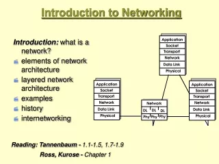
Using layers to analyze problems in a flow of materials • The concept of layers is used to describe communication from one computer to another. • The information that travels on a network is generally referred to as data or a packet. • A packet is a logically grouped unit of information that moves between computer systems. • As the data passes between layers, each layer adds additional information that enables effective communication with the corresponding layer on the other computer.
Networking Models • The historical and technical standard of the Internet is the TCP/IP model • The U.S. Department of Defence created the TCP/IP reference model, to design a network that could survive any conditions, including a nuclear war • Application layer handles issues of representation, encoding, and dialog control. • Transport layer deals with the quality of service issues of reliability, flow control, and error correction. • Internet layer is to divide TCP segments into packets and send them from any network. Best path determination and packet switching occur at this layer. • Network Access layer (aka host-to-network layer) concerned with all components, both physical and logical, that are required to make a physical link .
Application Layer • Trivial File Transfer Protocol (TFTP) • File Transfer Protocol (FTP) • Network File System (NFS) • Simple Mail Transfer Protocol (SMTP) • Simple Network Management Protocol (SNMP) • Domain Name System (DNS)
Transport Layer • TCP and UDP • Segmenting upper-layer application data • Sending segments from one end device to another end device • TCP only • Establishing end-to-end operations • Flow control provided by sliding windows • Reliability provided by sequence numbers and acknowledge me
Internet Layer • The purpose of the Internet layer is to select the best path through the network for packets to travel • IP provides connectionless, best-effort delivery routing of packets. • Internet Control Message Protocol (ICMP) provides control and messaging capabilities. • ARP resolves MAC address, for known IP addresses. • Reverse Address Resolution Protocol (RARP) determines IP addresses when the MAC address is known
Network Access Layer The network access layer defines the procedures for interfacing with the network hardware and accessing the transmission medium. Drivers for software applications, modem cards and other devices operate at the network access layer
Open Systems Interconnection model (OSI Model) • The OSI reference model was released in 1984 to help network builders implement networks that could communicate (interoperability). • The OSI reference model is the primary model for network communications. • The process of moving information between computers is divided into seven smaller and more manageable steps. • Reduces complexity • Standardizes interfaces • Facilitates modular engineering • Ensures interoperable technology • Accelerates evolution • Simplifies teaching and learning
Open Systems Interconnection model (OSI Model) Source Destination DATA Application Application Presentation Presentation DECAPSULATION Session Session ENCAPSULATION SEGMENT Transport Transport PACKET Network Network FRAME Data-Link Data-Link BITS Physical Physical 0101010101010101010
OSI Top 3 Layers – Application issues • Application • provides network services to the user's applications • file, print, message, database and application services • HTTP, SMTP, FTP • Presentation • responsible for manipulating data’s appearance as needed by the Application layer • Data encryption, compression and translation services • JPEG, MIDI, QuickTime, EBCDIC to ASCII • Session • establish and maintain communication between two hosts • Dialogue control • NFS, SQL, RPC
OSI Lower 4 Layers – Data Transport issues • Transport • PDU (protocol data unit) – Segment • the transport layer establishes, maintains, and tears down virtual circuits • Windowing • TCP and UDP • Network • PDU - Packet • Routing • Data packets and route update packets • connectivity and path selection between two hosts • Data-Link • PDU - Frame • physical addressing, network topology, network access, error notification, ordered delivery of frames, and flow control • Ethernet LCC and MAC layers • Physical • PDU – bits • Cabling, standards
TCP/IP Vs OSI • Similarities of the OSI and TCP/IP models: • Both have layers • Both have application layers, though they include very different services • Both have comparable transport and network layers • Packet-switched, not circuit-switched, technology is assumed • Networking professionals need to know both models • NOTE:Circuit switching is a methodology of implementing a telecommunications network in which two network nodes establish a dedicated communications channel (circuit) through the network before the nodes may communicate. The circuit guarantees the full bandwidth of the channel and remains connected for the duration of the communication session. The circuit functions as if the nodes were physically connected as with an electrical circuit.
Differences of the OSI and TCP/IP models: • TCP/IP combines the presentation and session layer into its application layer • TCP/IP combines the OSI data link and physical layers into one layer • TCP/IP appears simpler because it has fewer layers • TCP/IP transport layer using UDP does not always guarantee reliable delivery of packets as the transport layer in the OSI model does
Connecting Devices Networking Devices Internetworking Devices Repeaters Bridges Routers Gateways


![1. Introduction and Fundamental Concepts [1]](https://cdn1.slideserve.com/1709755/1-introduction-and-fundamental-concepts-1-dt.jpg)