Download
1 / 30
370 likes | 785 Vues
GE Zenith Capabilities - Overview. Paralleling Switchgear (PSG). GE Zenith Controls – Paralleling Switchgear (PSG). First system built in 1975 Currently ~ 150 systems/year Currently building project #1280. Exit. What is a P aralleling S witch g ear System ( PSG ) ?.

E N D
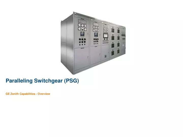
GE Zenith Capabilities - Overview Paralleling Switchgear (PSG)
GE Zenith Controls – Paralleling Switchgear (PSG) • First system built in 1975 • Currently ~ 150 systems/year • Currently building project #1280
Exit What is a Paralleling Switchgear System (PSG) ? Controls and switchgear, acting as a system, to manage & distribute emergency power and/or reduce energy costs thru intelligent use of local generation Genset #3 Genset #2 Genset #1 Utility Breaker Service Entrance Breaker Paralleling Breaker Paralleling Bus Primary Source (Normally Energized) Normal System (Normally Energized) Emergency System (Normally De-energized) Distribution Breakers ATS Critical Loads
Key Benefits of PSG? • Increased Backup Power Supply Capacity • When backup supply needs are > capacity 1 Gen • Backup Supply Redundancy • Provides “N + 1,2,etc” redundancy. Critical loads not reliant on only 1 Genset • Operational Flexibility • Ability to switch loads between multiple sources (including Gensets) for maintenance & test without interrupting power to the loads • Reduced Energy Bills • Turn on-site generation capability into an money-saving Asset, with start/stop/loading intelligence for reduced energy & demand charges.
Typical Systems built by GE Zenith Controls • Single Genset – Single Utility Soft Load Transfer Switch • For small facility standby & distributed generation • Multiple-Genset Standby • For Life Safety or Business Critical standby power to selected high-priority loads. • Utility Paralleling, Peak Shaving • Paralleling of Generator(s) and Utility supplies for backup of entire facility and reduced energy charges. • Mission Critical Standby • Turning on-site generation capability into an Asset, with start/stop/loading intelligence for reduced energy & demand charges.
Type 1 – Single Gen, Single Utility Soft Load Transfer Switch
Soft Load Transfer Switch Single Gen, Single Utility Architecture Utility Supply Building Dist. System Speed Control Gen Supply Breaker Utility Supply Breaker Generator GCB MCB Engine (N/O) (N/C) Standby Generator Building Load
Sequences of Operation – Softload Transfer Switch Utility Status: Gen Status: Mode: Energized. kW Varies. kW = Facility Load Normal OFF GCB MCB Genset/Backup Supply Utility/Primary Supply Critical Load Running. kW Varies. kW = Facility Load Failed/Off. Standby Running. Initial kW= 0kW Final kW= Facility Load Running. Initial kW = Facility Load Final kW= ~10% Rated Soft Re-Transfer To Utility kW kW GCB MCB
Sequences of Operation – Softload Transfer Switch Utility Status: Gen Status: kW Level kW Level Baseload Setpoint Mode: Energized. kW Varies. kW = Facility Load in excess Of Fixed Gen kW Running. kW Fixed. kW = Preset/ Fixed (typically 80-100% Genset Capacity) Base Load Mode Time Time GCB MCB kW kW kW kW Level Time Energized. kW Fixed. kW = Fixed Import or Export Level (kW) Running. kW Varies. kW = Facility Load in excess Of Import Setpoint Import (Export) Mode kW Level kW Level Import Setpoint Time Time GCB MCB kW kW kW kW Level Time
Control Panel – Softload Transfer Switch Generator & Utility Protection via: GE Multilin G30 ™ LAN/ WAN Peak Shaving Control via: Woodward GCP-32 ™ Peak Shaving Controller communications via: Woodward GW4 ™ (Modbus) Local Monitoring and email Alarm transmission via: Enervista Viewpoint Monitoring ™ Plus: Manual Control Switches Safety Lockout/86 Relay LED Status Annunciation
Site Level: Peak Shave System Metering Meter #1: Utility Meter (UM) : Utility Supply kW, Energy, etc. Meter #2: Generator Meter (GM) : Generator Supply kW, Energy, etc. Virtual Meter #1: Load Meter (LM = GM + UM) {Developed in GE Aggregator ™} Peak Shaving Savings = (LM * Rate Structure) – (UM * Rate Structure) GE Multilin G30 Relay Meter #2: Utility Source Metering (UM) Meter #1: Generator Source Metering (GM) V (PT’S) V (PT’S) 3 CT’s 3 CT’S Closed Transition ATS or 5-cycle CB’s Utility Supply GCB MCB Engine Generator Genset Supply Critical Load
Peak Shave Savings Reports – GE Aggregator™ Setup Utility billing structure 1 Export reports for printing, sending, or filing 2 Setup custom site bills (showing usage or savings) 4 Enter Begin & End dates & create/ view bills 3
Local & Remote Access to Reports LEVEL 4: Enterprise Energy Aggregator™ Viewers (Up to 5 concurrent users) Web Server View reports from EEA. LEVEL 3: Enterprise Energy Aggregator™ (EEA) (Qty. 1) “Aggregates”, or combines date from from the (6) REA servers. LEVEL 2: Regional Energy Aggregator™ (REA) (1 Server/~100 Sites) … Est. (6) REA’s for full 630-site configuration Up to ~ 100 Sites per Aggregator Upload Data-Logs LAN or VPN Local data-logging by Multilin G30’s Site Level Site Peak Shaving Control Systems w/ local GE Enervista Viewpoint™ Unlimited # Sites GE Zenith ZTSSL GE Zenith ZTSSL
GE Zenith Design Recommendations • True PQ Metering of Both Sources, including Waveform and Events Capture – for quick diagnosis of system events and outages • Utility grade protective relaying for equipment and personnel safety - – due to extended nature of utility paralleling. • Open protocol Modbus communications for easy facility integration • Plug-and-Play PC Monitoring for low cost, but effective system monitoring and alarm management, including automatic email generation of any/all alarm events • Key-lockable Control Switches for safety • Automatic report generation for: Utility and Generator Energy supply (kWH), Demand (kW), and Peak Shave savings (based on site-specific utility rate structure).
Exit Multiple Genset Standby Typical Architecture Genset #3 Genset #2 Genset #1 Primary Distribution Paralleling Bus Secondary Distribution Emergency Loads Emergency Panelboard ATS
Typical Sequence of Operation for PSG – On loss of Utility Synchronous Conditions 1) Volts within +/- 10% 1 2) Phase within +/- 20 Deg 1 2 X Genset #2 Genset #1 Paralleling Bus ATS PSG Controls synchronize 2nd and 3rd Gensets to Bus (speed and volts bias to Gen Gov & AVR), and close CB’s at point of synchonism (see above). 1 Utility Supply Fails 5 2 ATS Send start signal to all Gens 6 PSG Controls remove xfer inhibits on lower priority ATS to permit connection to Gen system. 3 All Gens start. PSG control system monitors. 1st Gen at rated Volts & Freq is connected to the Paralleling Bus. PSG Controls shed low priority ATS if Gens are overloaded. PSG permits manual or auto re-connect. 7 4 Priority 1 ATS Xfer to Gens. PSG inhibits xfer of lower priority ATS to prevent Gen overload. 8 PSG Controls shed low priority ATS if Gens are overloaded. PSG permits manual or auto re-connect.
Typical Sequence of Operation for PSG – On Return of Utility Genset #2 Genset #1 Paralleling Bus ATS 1 4 PSG controls hold start signal to all Gens to permit cooldown at no load. Utility Supply Returns ATS’s retransfer loads to Utility, after preset time delays, and remote start commands. 2 After cooldown timer expires, PSG controls remove start signals to Gensets. 5 When last ATS removes start command, PSG Controls open all Gen CB’s 3 Gensets shut down and remain ready for next utility outage. 6
Typical GE Zenith Configuration Other key items (inside) • GE Fanuc PLC (Single or Redundant) • Flexible Woodward SPMA (sync) and LSM (load Sharing) modules • Hardwired backup switches for load add/shed • Backup 24 VDC power supply for system ride-thru on DC control power problems Key Items – GE Recommendation • Highly visible, LED Annunciation for instant viewing and viewing from distance • Full manual paralleling control switches (Auto/Manual, Sync Switch, CB Open/close, Synchroscope/V/Hz meters on swing panel) • Generator Analog Metering for best viewing of Gen & Utility stability • Generator Protective Relay (typically Utility grade for MV, Industrial grade for LV) • Totalizing Power Quality Meter (PQM) with waveform & diagnostic capability • Simple Operator Interface Panel (OIP) for setup of time delays, load add/shed, etc.
Utility Paralleling, Peak Shaving Typical Architecture • Generators sized to high% of total facility loads • Utility CB and Gen CB’s act as a “Transfer Switch”, switching 2 sources of power to main bus in event of Utility outage. • Re-transfer to utility either Open or Closed Transition (typically closed) • Main bus is fed from 2 sources power – utility supply (primary) and generator supply (backup) • Bus AIC/Short circuit rating sized to capacity of utility + all Gensets. Utility Supply Genset Breakers Feeder Breakers Main Bus Facility Loads
Utility Paralleling - Base Loading Genset Base Load: Utility kW Level 1 Utility Supply Available Baseload Setpoint Time kW Gen kW Level Utility Supply When pre-programmed conditions for Genset starting satisfied (Utility load >x, time of day, etc) PSG Controls start Gensets, synchonize to utility supply, and close Gen CB’s. 2 kW Time GCB kW PSG system controls kW on Gensets to fixed, base load level. 3 GCB As system load varies, Utility supply kW varies to supply the load. 4 kW When Gen supply no longer needed, PSG Controls slowly ramp load back to utility supply and open Gen CB;s at near no-load. 5 kW Load kW Level PSG controls cooldown and shutdown Gensets. 5 Time
Utility Paralleling - Import/Export Utility Import/Export: Baseload Setpoint Utility kW Level 1 Utility Supply Available Time Gen kW Level MCB When pre-programmed conditions for Genset starting satisfied (Utility load >x, time of day, etc) PSG Controls start Gensets, synchonize to utility supply, and close Gen CB’s. 2 kW Time GCB kW PSG system controls kW on Gensets to maintain fixed kW value on Utility supply (import or export). 3 GCB As system load varies, Genset supply kW varies to supply the load. 4 kW When Gen supply no longer needed, PSG Controls slowly ramp load back to utility supply and open Gen CB;s at near no-load. 5 kW Load kW Level Time PSG controls cooldown and shutdown Gensets. 5
Typical GE Zenith Configuration Other key items (inside) • GE Fanuc PLC (Single or Redundant) • Flexible Woodward SPMA (sync) and LSM (load Sharing) modules • Hardwired backup switches for load add/shed • Backup 24 VDC power supply for system ride-thru on DC control power problems Key Items – GE Recommendation • Highly visible, LED Annunciation for instant viewing and viewing from distance • Full manual paralleling control switches (Auto/Manual, Sync Switch, CB Open/close, Synchroscope/V/Hz meters on swing panel) • Full, Open transition, manual control of Utility CB • Generator Analog Metering for best viewing of Gen & Utility stability • Generator Protective Relay (Utility grade) • Totalizing Power Quality Meter (PQM) with waveform & diagnostic capability • Industrial Computer with graphical 1-lines, load controls, trending, alarm management.
Mission Critical Standby Typical Architecture – Tier 4 Data Center System ‘B’ Gen Bus System ‘A’ Gen Bus System ‘A’ Utility Bus System ‘B’ Utility Bus Gen A Util B Util A Gen B Unit Subs Unit Subs Gen B Util A Unit Subs Util B Gen A Unit Subs • Complete system redundancy – Tier 4 classification • 100% Backup Generator N+1 capacity • 2 x Independent Gen Paralleling systems, each capable of 100% backup & control of other system (GE Zenith-Fanuc unique design for Quadruple redundancy!
Typical GE Zenith Configuration Util ‘B’ Util ‘A Gen ‘B’ Gen ‘A’ Key Items – GE Recommendation • Full Manual backup, visible LEDs, Utility Grade relaying, PQ Metering • Synchronized-backup PLC each Gen System (2 x PLC each Gen system) • Gen System Graphical Display, + large monitor each system for display downstream load status • Each System Master control capable backup of other system


![Tempat Pkl Di Bekasi Barat 0831–4506–0500[WhatsApp]](https://cdn5.slideserve.com/10199480/tempat-pkl-di-bekasi-barat-0831-4506-0500-whatsapp-dt.jpg)


![Tempat Praktek Industri Smk Administrasi Perkantoran 083I 4506 0500[WhatsApp]](https://cdn5.slideserve.com/10291423/tempat-praktek-industri-smk-administrasi-dt.jpg)

![Tempat Prakerin Smk Manajemen Kantor Di Jogja Ô83I-45Ô6-Ô5ÔÔ[WA]](https://cdn5.slideserve.com/10334019/tempat-prakerin-smk-manajemen-kantor-di-jogja-dt.jpg)