Download
1 / 68
680 likes | 718 Vues
Learn about interfacing between Input/Output devices and the CPU, including parallel and serial ports, signal lines, registers, and serial communication standards. Explore common modes, hardware components, and connecting devices via serial cables.

E N D
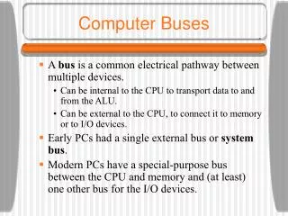
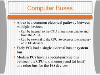
Interfacing Interfacing between Input/Output devices and the CPU is must for a system. Because both the input and output devices have specific electrical characteristics, that are often different than the technology of the CPU. In case of switches being used as input devices, then the problem of ‘bouncing’ of the switch must be taken into account and must be compensated. Or to use an output device, translation is often needed to convert output signals of the CPU to a format that the output device can use. Port, which is generally accompanied with each system, is used by each input and output devices for communication with the system.
Port Port is a set of signal lines that the microprocessor in CPU uses to exchange data with devices such keyboard, modem, drives, printers, displays. Port Type 1. Parallel Port 2. Serial Port
Parallel Port • Multiple bits are transmitted in parallel at once. • Parallel port is a simple and inexpensive tool for building computer controlled devices. • Simple in use and easily programmable. • The primary use is to connect printers to computer, so often called as Printer Port. • A 25 pin female (DB25) connector is attached in almost all PC in the rear panel.
Parallel Port Types • Original (SPP): This is Standard Parallel Port. SPP can transfer eight bits at once to a peripheral. It uses nibble mode for data transfer. • PS/2-type (Simple Bi-directional): It is bi-directional port. It can transfer eight bits at once to a peripheral. • EPP (Enhanced Parallel Port): It is bi-directional port. It can switch the direction for data transfer quickly. • ECP (Extended Capabilities Port): It is bi-directional port. It has its own buffers and support for direct memory access transfers and data compression. • SCSI (Small Computer System Interface): Allows up to seven devices to connect to a PC along a single cable. • Multi-mode Ports: The ports that can emulate some or all of the above types of port.
Parallel Port Modes • Compatibility Mode • Nibble Mode • Byte Mode • EPP • ECP
The lines in DB25 connector are divided in to three groups, they are 1) Data lines (data bus) 2) Control lines 3) Status lines • Data is transferred over data lines. • Control lines are used to control the peripheral and the peripheral returns status signals back to computer through Status lines.
Parallel Port Registers • The registers found in standard parallel port are, 1) Data register 2) Status register 3) Control register
Serial Communication Serial communication is the most common low-level protocol for communicating between two or more devices. Normally, one device is a computer, while the other device can be a modem, a printer, another computer, or a scientific instrument such as an oscilloscope or a function generator. As the name suggests, the serial port sends and receives bytes of information in a serial fashion - one bit at a time. These bytes are transmitted using either a binary (numerical) format or a text format.
Serial Port Interface Standard The serial port interface for connecting two devices is specified by the TIA/EIA-232C standard published by the Telecommunications Industry Association. The original serial port interface standard was given by RS-232, which stands for Recommended Standard number 232. The term "RS-232" is still in popular use. RS-232 defines these serial port characteristics: 1. The maximum bit transfer rate and cable length. 2. The names, electrical characteristics, and functions of signals. 3. The mechanical connections and pin assignments.
Connecting Two Devices with a Serial Cable The RS-232 standard defines the two devices connected with a serial cable as the Data Terminal Equipment (DTE) and Data Circuit-Terminating Equipment (DCE). This terminology reflects the RS-232 origin as a standard for communication between a computer terminal and a modem. Because RS-232 mainly involves connecting a DTE to a DCE, the pin assignments are defined such that straight-through cabling is used, where pin 1 is connected to pin 1, pin 2 is connected to pin 2, and so on. A DTE to DCE serial connection using the transmit data (TD) pin and the receive data (RD) pin is shown below.
If you connect two DTE's or two DCE's using a straight serial cable, then the TD pin on each device are connected to each other, and the RD pin on each device are connected to each other. Therefore, to connect two like devices, you must use a null modem cable. As shown below, null modem cables cross the transmit and receive lines in the cable.
Serial Port Signals and Pin Assignments • Serial ports consist of two signal types: data signals and control signals. To support these signal types, as well as the signal ground, the RS-232 standard defines a 25-pin connection. However, most PC's and UNIX platforms use a 9-pin connection. In fact, only three pins are required for serial port communications: one for receiving data, one for transmitting data, and one for the signal ground. • The pin assignment scheme for a 9-pin male connector on a DTE is given below.
The pins and signals associated with the 9-pin connector are described below. Refer to the RS-232 standard for a description of the signals and pin assignments used for a 25-pin connector.
Signal States • Signals can be in either an active state or an inactive state. An active state corresponds to the binary value 1, while an inactive state corresponds to the binary value 0. An active signal state is often described as logic 1, on, true, or a mark. An inactive signal state is often described as logic 0, off, false, or a space. • The "on" and "off" states for a data signal and for a control signal are shown below.
The Data Pins • Most serial port devices support full-duplex communication meaning that they can send and receive data at the same time. Therefore, separate pins are used for transmitting and receiving data. For these devices, the TD, RD, and GND pins are used. However, some types of serial port devices support only one-way or half-duplex communications. For these devices, only the TD and GND pins are used. In this guide, it is assumed that a full-duplex serial port is connected to your device. • The TD pin carries data transmitted by a DTE to a DCE. The RD pin carries data that is received by a DTE from a DCE.
The Control Pins 9-pin serial ports provide several control pins that: Signal the presence of connected devices Control the flow of data The control pins include RTS and CTS, DTR and DSR, CD, and RI. • The RTS and CTS Pins. The RTS and CTS pins are used to signal whether the devices are ready to send or receive data. This type of data flow control - called hardware handshaking - is used to prevent data loss during transmission. When enabled for both the DTE and DCE, hardware handshaking using RTS and CTS follows these steps: 1. The DTE asserts the RTS pin to instruct the DCE that it is ready to receive data. 2. The DCE asserts the CTS pin indicating that it is clear to send data over the TD pin. If data can no longer be sent, the CTS pin is unasserted. 3. The data is transmitted to the DTE over the TD pin. If data can no longer be accepted, the RTS pin is unasserted by the DTE and the data transmission is stopped.
The DTR and DSR Pins. Many devices use the DSR and DTR pins to signal if they are connected and powered. Signaling the presence of connected devices using DTR and DSR follows these steps: 1. The DTE asserts the DTR pin to request that the DCE connect to the communication line. 2. The DCE asserts the DSR pin to indicate it's connected. 3. DCE unasserts the DSR pin when it's disconnected from the communication line. • The DTR and DSR pins were originally designed to provide an alternative method of hardware handshaking. However, the RTS and CTS pins are usually used in this way, and not the DSR and DTR pins. However, you should refer to your device documentation to determine its specific pin behavior.
The CD and RI Pins. The CD and RI pins are typically used to indicate the presence of certain signals during modem-modem connections. • CD is used by a modem to signal that it has made a connection with another modem, or has detected a carrier tone. CD is asserted when the DCE is receiving a signal of a suitable frequency. CD is unasserted if the DCE is not receiving a suitable signal. • RI is used to indicate the presence of an audible ringing signal. RI is asserted when the DCE is receiving a ringing signal. RI is unasserted when the DCE is not receiving a ringing signal (for example, it's between rings).
Serial Data Format • The serial data format includes one start bit, between five and eight data bits, and one stop bit. A parity bit and an additional stop bit might be included in the format as well. The diagram below illustrates the serial data format. • Number of data bits - parity type - number of stop bits
Synchronous and Asynchronous Communication • The RS-232 standard supports two types of communication protocols: synchronous and asynchronous. • Using the synchronous protocol, all transmitted bits are synchronized to a common clock signal. The two devices initially synchronize themselves to each other, and then continually send characters to stay synchronized. Even when actual data is not really being sent, a constant flow of bits allows each device to know where the other is at any given time. That is, each bit that is sent is either actual data or an idle character. Synchronous communications allows faster data transfer rates than asynchronous methods, because additional bits to mark the beginning and end of each data byte are not required. • Using the asynchronous protocol, each device uses its own internal clock resulting in bytes that are transferred at arbitrary times. So, instead of using time as a way to synchronize the bits, the data format is used. • In particular, the data transmission is synchronized using the start bit of the word, while one or more stop bits indicate the end of the word. The requirement to send these additional bits causes asynchronous communications to be slightly slower than synchronous. However, it has the advantage that the processor does not have to deal with the additional idle characters. Most serial ports operate asynchronously.
Bits Transmitted • By definition, serial data is transmitted one bit at a time. The order in which the bits are transmitted is given below: 1. The start bit is transmitted with a value of 0. 2. The data bits are transmitted. The first data bit corresponds to the least significant bit (LSB), while the last data bit corresponds to the most significant bit (MSB). 3. The parity bit (if defined) is transmitted. 4. One or two stop bits are transmitted, each with a value of 1. • The number of bits transferred per second is given by the baud rate. The transferred bits include the start bit, the data bits, the parity bit (if defined), and the stop bits.
Start and Stop Bits • Most serial ports operate asynchronously. This means that the transmitted byte must be identified by start and stop bits. The start bit indicates when the data byte is about to begin and the stop bit(s) indicates when the data byte has been transferred. The process of identifying bytes with the serial data format follows these steps: • When a serial port pin is idle (not transmitting data), then it is in an "on" state. • When data is about to be transmitted, the serial port pin switches to an "off" state due to the start bit. • The serial port pin switches back to an "on" state due to the stop bit(s). This indicates the end of the byte.
Data Bits • The data bits transferred through a serial port might represent device commands, sensor readings, error messages, and so on. The data can be transferred as either binary data or ASCII data. • Most serial ports use between five and eight data bits. Binary data is typically transmitted as eight bits. Text-based data is transmitted as either seven bits or eight bits. If the data is based on the ASCII character set, then a minimum of seven bits is required because there are 27 or 128 distinct characters. If an eighth bit is used, it must have a value of 0. If the data is based on the extended ASCII character set, then eight bits must be used because there are 28 or 256 distinct characters.
The Parity Bit • The parity bit provides simple error (parity) checking for the transmitted data. The types of parity checking are given below. • The parity checking process follows these steps: • The transmitting device sets the parity bit to 0 or to 1 depending on the data bit values and the type of parity checking selected. • The receiving device checks if the parity bit is consistent with the transmitted data. If it is, then the data bits are accepted. If it is not, then an error is returned.
USB (Universal Serial Bus) • With the limitation of parallel port and serial port attached with PC, only a few peripherals can be connected to the PC. USB overcomes this limitation. The Universal Serial Bus gives a single, standardized, easy-to-use interface to connect up to 127 devices to a computer. Each device can consume up to a maximum of 6 megabits per second (Mbps) of bandwidth, which is fast enough for the many of peripherals devices.
Benefits of USB • Ease of use : simply plug in it without rebooting the PC • One Interface for many devices: USB is flexible enough to be used with many kind of peripherals. Instead of having a different connector type and supporting hardware for each peripheral, one interface serves many.
Benefits of USB • Automatic Configuration: When a user connects a USB peripheral to a powered system, windows automatically detects the peripheral and loads the appropriate software driver. Only when first time the peripheral connects, Windows may prompt the user for driver, but once only. Even no need of rebooting of the system after installing the driver.
Benefits of USB • No user settings: USB peripherals don’t have user-selectable setting such as port address and interrupt-request (IRQ) lines. • Easy to connect: With USB, there’s no need to open the computer’s enclosure to add an expansion card for each peripheral. A PC has at least two USB ports. • Simple Cables: The USB’s cables can be as long as 5 meters. With hubs, a device can be as far as 30 meters from its host PC. The following figure shows a typical four-port hub.
Benefits of USB • Hot pluggable: We can connect and disconnect a peripheral whenever we want, whether or not the system or peripheral are powered, without damaging the PC or peripheral. The operating system detects when any device is attached and readies it for use.
Benefits of USB • No power supply required: The USB interface includes power-supply and ground lines that provide +5V from the computer or hub supply. A peripheral that requires up to 500 milli amperes can draw all of its power from the bus instead of having its own supply. In contrast, most other peripherals have to choose between including a power supply in the device or using a bulky and inconvenient external supply.
Benefits of USB • Speed: USB supports three bus speeds: high speed at 480 Megabits per second, full speed at 12 Megabits per second, and low speed at 1.5 Megabits per second.
Working Style of USB • Physical: USB connections are made externally to the PC that contains the "host controller". Hubs permit a "hierarchical star" or tree-like topology of interconnection, where the PC is at the root. Standard USB cables having an "A" series connector on one end, and a "B" series connector on the other, are used between devices.
Figures of USB Connector A typical USB “B” connector A typical USB “A” connector
For example, a cable between the host PC and a hub would have an "A" plug at the PC (root) connection and a "B" plug for the hub's upstream port receptacle. End node devices (or other hubs) would then attach to the hub's downstream "A" receptacles with standard "A-B" cables or with integral USB cables that have an "A" plug incorporated at the upstream end. Cables may be up to 5 meters in length (up to 3m for low speed devices), and incorporate 2 pairs of wires - one pair carries the USB data signaling, and the other pair carries power to "bus-powered" devices. Cables for high-speed device attachment are shielded to prevent electromagnetic interference; low speed cables do not require shielding. Hubs can be attached to other hubs - a "chain" of up to five hubs can exist between any device and the root host controller, giving a maximum distance of 30 meters from the PC to the end node device. And the chained hubs must be "self-powered" in order to meet power distribution requirements.
Electrical • The Universal Serial Bus carries data between the host controller and nodes using differential drivers and in a bi-directional, half-duplex mode. Data is sent using NRZI encoding (transition on a "0", none on a "1") permitting an efficient and robust transmission channel. "Bit-stuffing" (insertion of a "0" after six consecutive "1"s at the source, with removal at the receiving end) is employed with the NRZI encoding to ensure sufficient transitions to maintain synchronization.
Electrical • The signaling rate for high speed devices is 12 million per second; with NRZI 1bit per code this yields a nominal 12 megabits per second (MBPS) data transfer rate, or equivalently, 1.5 megabytes per second (MBPS). Low speed devices drive the bus at 1/8 the high-speed rate, resulting in a nominal 1.5 MBPS or 187.5 KBPS. Overhead for framing and packet zing along with bit-stuffing will cause the available bandwidth to be somewhat less than these nominal values.
Electrical • USB devices can be either "self-powered" or "bus-powered". Self-powered devices obtain their energy from a source independent of the USB, for example using batteries or an AC-DC converter. Devices that use less than 500 milli amperes (mA) may be bus-powered from the USB, making use of the nominal 5 volt DC available on the second pair in the cable. An energy-saving feature provides that devices may be placed into a "suspended" state in which they are only permitted to draw 1/2mA until given a "wake-up" or "resume" command.
Logical • A Universal Serial Bus installation requires a USB host and one or more USB devices. One or more intervening USB hubs may also be present. • A USB host system includes: • Client Software -- associated with controlling the USB device's functions. Client S/W interfaces with host application software and the USB system software, and is generally unique to the device. • USB system software (e.g. system device drivers) for the USB host controller -- generally common code supplied by the host's operating system. • USB host controller and bus interface hardware.
A USB device includes: • USB device controller and bus interface hardware. • Device specific hardware to control unique functional interfaces, buffer data, etc. • Device specific software (or "firmware") to interface with the USB device controller and device specific hardware. This SW handles USB communications - commands, status, and data transfers, and interacts with the client SW in the host to control functional interfaces in the device.
A USB hub includes: • Upstream attachment port to a USB host or another hub. • One or more downstream ports for attaching USB devices or hubs. • USB hub controller and bus interface hardware and firmware to control hub functions. Hubs repeat bus transmissions in both directions and notify the host when the addition or removal of a device is detected.
The timing of transmissions on the USB is defined by "frames". A frame time is 1 ms and a special packet called Start of Frame (SOF) signals it’s beginning. The host controls all timing, although provision is also made for synchronization with an external source. All transactions on the USB are initiated by the host and take the form of one or more packets.
There are four types of USB transfers, optimized for the requirements of different clients and functions: • Control transfers - support device configuration, command, and status flows. • Interrupt transfers - support devices that have infrequent small data transfers, but a bounded service period requirement (e.g. keyboard, mouse, and joystick).
Bulk transfers - support devices that require larger amounts of transmission bandwidth and require guaranteed delivery of data, but can afford to wait a reasonable amount of time for the transfer to take place (e.g. asynchronous modems, scanners, and printers). • Isochronous transfers - support devices which require guaranteed access and bounded latency, but have enough intrinsic redundancy that loss of some limited number of packets can be tolerated (e.g. voice telephony, audio CD playback, and digitized video).
Inside a USB cable there are two wires for power -- +5 volts (Red) and ground (Brown) – and a twisted pair (Yellow and Blue) of wires to carry the data. The following figure shows the USB cable.